Download
1 / 35
450 likes | 649 Vues
Challenges in the pattern information-transfer channel. Mike Rieger Hillsboro, OR. Outline. T he challenges: Smaller features. Higher feature density. A t decreasing cost / function . Survey new lithography & process technologies to address those challenges .

E N D
Challenges in the pattern information-transfer channel Mike Rieger Hillsboro, OR
Outline • The challenges: • Smaller features. • Higher feature density. • At decreasing cost / function. • Surveynew lithography & process technologies to address those challenges. • Focus on information density (not just linewidth) • Outline layout constraints required to enable lithography innovations.
Information density in a microlithographicimage 30 mm 30 nm ½ inch 8 miles
The pattern communication channel Light OPC/RET IC Layout Mask Layout Source MDP & PG Mask Lens • Modern scanner lens • f/ 0.55 • 5000lp/mm • 26mm field http://www.zeiss.com/ Wafer
Information capacity of the lithography channel is growing more slowly than Moore’s Law Scanning OPC & process l & Optics (NA) Tomoyuki Matsuyama, et al, Nikon, 2006
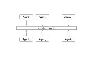
Information theory perspective Information channel Source encode decode Destination C Message (Design Layout) Copy of Message (structures on chip) Noise Channel capacity is fundamentally limited by the bandwidth and the signal to noise ratio. CaBW * Log(S/N) from C.E. Shannon, A Mathematical Theory of Communications,1948
Information contained in a sample design layout (logic, 40nm node) Bits per transistor (flattened layout) • Transistor density = 3.2 M transistors/ mm2 Assumption: 32 + 32 bits per polygon vertex. RTL (9-bits/transistor) is hierarchic
Information density in the channel Light OPC/RET IC Layout Mask Layout Source 240 MBytes/mm2 (M1 layout, 40nm node) MDP & PG Mask 500-1000 MBytes/mm2 (1x scale) Lens 178 MBytes/mm2 (193i, NA=1.35) EUV 1240MBytes/mm2 (13.5, NA= 0.25) Wafer
Improving Channel effectiveness • Fouroptions: • Increase spatial bandwidth • Optics & illumination • Increase Signal to Noise ratio in channel. • Add more “parallel” channels. • “Compress” information: • Use lithography and process innovations to supply missing information, thus lower process entropy. 3. Additional channels Channel capacity C 1. Increase bandwidth 2. Lower noise CaBW * Log(S/N) 4. Lower process & layout entropy Information through channel
Increase bandwidth: wavelength & opticsCaBW * Log(S/N) micron ArF wavelength in water (145nm) Immersion (adapted from) Mark Bohr, SPIE 2011
Increase bandwidth: Multiple exposure strategiesCa N*BW * Log(S/N) Double exposure lithography Pitch splitting contacts Amyn Poonawala, Computer Engineering Department, U. of California, Santa Cruz Yan Borodovsky, Portland Technology Department, Intel Corp. PeymanMilanfar, Electrical Engineering Department, U. of California, Santa Cruz lines • Costs of multiple exposure methods: • Reduced litho throughput. • Increased mask cost • Layout “colorability” restrictions. Layouts courtesy of IMEC; coloring by Synopsys
Resist BARC 1st trench imaging HM LowK Etch stop…. Hard Mask etchResist/BARC strip 2nd trench imaging Hard Mask etchResist/BARC strip transfer to dielectric Double Patterning – LELE pitch splitting V. Wiaux, et. al. SPIE Vol. 6924-08, 2010
Lower systematic noise with OPCCaBW * Log(S/N) Mask Simulate Iterate - Adjust Shapes Compare + Wafer Design Intent OPC removes predictable, localized feature distortions
Effects of off-axis illumination on-axis off-axis source condenser lens mask lens • better contrast • better DOF diffraction orders
Optimizing sources for design layout pattern James Blatchford, TI, SPIE 2011
Cost of source optimizationLayout is restricted to pitches defined by the source Dipole source X Low noise for this pattern Can’t resolve this pattern ü Custom source • Physical noise sources are unaffected. • A custom source makes layout patterns with certain spatial frequencies more immune to noise; • But other layout configurations will be more susceptible. • Design layouts must conform to spatial frequency • constraints.
Mask optimization with subresolution assist features Contacts Lines Assist features (SRAFs) generate spatial frequency components in the mask layout consistent with specific source configurations
Mutual information between design and process Information channel Source encode decode Destination C bits a bits Message (Design Layout) Copy of Message (structures on chip) fixed mutual information Source governs SRAF placement Source defines allowed and disallowed pitches in layout
Constant-width features defined by SAPD process Sidewall-aligned pitch doubling (SAPD) Width of printed structures is constant everywhere and determined by the process exposed pattern Spacer will form closed loops everywhere, and they must be “cut” with a second mask exposure and process step to form useful features. result
SAPD for 2D layouts design add sidewall features first exposure trim exposure final pattern Yongchan Ban, U. Texas, et al, SPIE 2011
Complementary Patterning Grating pattern is mutually known to process and design. • Relevant information is the set of cut locations & sizes. • Relatively sparse (low duty cycle) • relaxed tolerance for placement uncertainty:
Directed self assembly (DSA) materials Unguided behavior Density multiplication Guided JSR, IBM, nextbigthing.com
Materials (hypothetical) solution to LER from shot noise apply “stiff” directed material low photon density, high sensitivity increase photon density such material won’t like sharp bends high photon density, low sensitivity
Productivity trends 1R. Kurtzweil, 2008 2IBS Vol 18 # 5, 2009 3IC Insights 4IBS Vol 18 #7, 2009 5Crestmont Research, 2010
Lithography tool cost EUV Long-term trend is 18% reduction in litho capital cost per transistor, per year.
Observations • EUV promises nearly an 7X increase in information density compared to 193i (1240 vs. 178 Mbytes/mm2 ) -- nearly a 3-generation shrink . • Very good for 2-D configurations, such as contacts, trim/cut patterns. • On a single layer, double patterning (pitch splitting and pitch doubling) doubles density, thus there is no net productivity gain (cost /feature same as single exposure). • At least DP does not increase cost per device. • Double-patterning provides a 2-generation shrink (50%) for 1-dimensional layouts; interactions between DP’d layers can provide device density increase up to 4X.
Conclusions • When design information exceeds available channel capacity, the litho process must lower entropy by limiting choices. • The missing information is provided by having more order (spatial structure) in the process, which must be accommodated in design layout constraints. • Materials & process will be playing an increasing role in “more Moore.” • Enable resolution and density. • Reduce cost. • Restricted pitches (spatial frequencies) are becoming a dominant layout constraint. • highly regular, repeating patterns are best. • Regular 1-D layouts provide compelling manufacturing benefits: • Low entropy maximizes optical image fidelity. • Defines realistic targets for self-assembling process technologies. • Maximizes the effectiveness of double patterning.
Acknowledgements Thank you John Stirniman, Lars Bomholt, Kevin Lucas, Thomas Schmoeller, Bob Lefferts.
Review: Nyquist sampling theorem A signal containing no frequencies higher than B can be exactly reconstructed from a series of samples spaced by ½ the period of B. Band-limited signal 1/B samples Reconstruction function convolved with samples Harry Nyquist, Certain Topics in Telegraph Transmission Theory, 1928
Review: Hartley’s Law Hartley’s Law extends Nyquist to express the information capacity of a channel in terms of bits/second, R. R <= 2B log2(MH) Where MHis the number of distinguishable levels per sample. Example: Max Amplitude uncertainty M = 14 levels (= 3.8 bits/sample) Min Ralph Hartley, Transmission of Information, 1928
Calculating information density of litho optics R <= 2B log2(MH) Square the Nyquistsample rate in Hartley’s Law, and replace Hz with: x,y sample spacing = Note that R is information density (not information within the circle)
Estimating MH sinusoidal image signal at minimum pitch ~ amplitude uncertainty ~4% of peak +/-5% each edge • Determining MH • Meeting +/-10% CD spec at minimum ½ pitch @ contrast = 0.5 is (roughly) equivalent to an amplitude uncertainty of 1:25
Optical information density calculations Optical density equation: ArF 193 immersion scanner: EUV 1st generation scanner: