Download
1 / 83
850 likes | 1.02k Vues
Function Generator Controller (FGC3) for power converter controls in the PSB. CERN Operator Training 2012. Quentin King TE-EPC-CC With thanks to all my colleagues in TE-EPC, BE-OP and BE-CO who have collaborated on the FGC project.

E N D
Function Generator Controller (FGC3) for power converter controls in the PSB CERN Operator Training 2012 Quentin King TE-EPC-CC With thanks to all my colleagues in TE-EPC, BE-OP and BE-CO who have collaborated on the FGC project.
CERN Operator TrainingFGC3 for power converter controls in the PSB • Corrector dipole and multipole power converter renovation in the PSB • Overview of power converter control • History of the FGC project • Features of the FGC3 • FGC system architecture • Working Sets/Knobs and function editor via INCA • OASIS • Alarms • Post Mortem • Expert interfaces • Use of FGC3 for other converters in the future
CERN Operator TrainingFGC3 for power converter controls in the PSB • Corrector dipole and multipole power converter renovation in the PSB • Overview of power converter control • History of the FGC project • Features of the FGC3 • FGC system architecture • Working Sets/Knobs and function editor via INCA • OASIS • Alarms • Post Mortem • Expert interfaces • Use of FGC3 for other converters in the future
1 Corrector circuit converter renovation in the PSB There are 488 corrector magnets organised in 254 circuits. The 146 existing power converters were installed between 1972 and 1978. They use many bipolar transistors in parallel to regulate the current from a common 30V DC-bus. 4-quadrant operation is achieved using a mechanical polarity switch, which only allows a few inversions per year. They are controlled by CAMAC, shared GFA’s and hybrid single transceivers since 1980. Only 8 different functions are available for all the corrector circuits.
1 Corrector circuit converter renovation in the PSB Old linear converters to be replaced by new switched-mode “ACAPULCO” converters 32 ACAPULCO converters will be used for dipole corrector circuits 82 ACAPULCO converters will be used for the multipole corrector circuits FGC_Ether FGC_Ether Gateway
1 Corrector circuit converter renovation in the PSB As now, there will be many more circuits (254) than converters (114). Patch cables are used to link to the circuits that are currently required to a converter. An FGC “device” is defined in the database for every circuit. E.g. BR1.DHZ3LY The identity of a circuit is linked to an FGC3 MAC address dongle: To Magnets Patch cables From converters
1 Corrector circuit converter renovation in the PSB Installation schedule 8 PCs with FGC3s installed on dipole circuits Working sets interface implemented and debugged 24 additional PCs with FGC3s installed on air-cooled dipole circuits Water-cooled dipoles magnets connected to the WIC system Post Mortems and alarms implemented and debugged Oasis interface implemented and debugged Dipole circuits fully validated by OP Old multipole magnets PCs and control dismantled 82 Additional PCs with FGC3s installed on multipole circuits Consolidated system commissioned and ready for operation
1 Corrector circuit converter renovation in the PSB Questions After the renovation, the number of dipole and multipole corrector circuits will be: • Less than the number of power converters • More than the number of power converters • The same as the number of power converters The power converter renovation is being done in two steps. In the first step in 2012: • The converters for the dipole corrector circuits are being replaced • The converters for the multipole corrector circuits are being replaced • The converters for a mix of dipole and multipole circuits are being replaced
CERN Operator TrainingFGC3 for power converter controls in the PSB • Corrector dipole and multipole power converter renovation in the PSB • Overview of power converter control • History of the FGC project • Features of the FGC3 • FGC system architecture • Working Sets/Knobs and function editor via INCA • OASIS • Alarms • Post Mortem • Expert interfaces • Use of FGC3 for other converters in the future
2 Overview of power converter control What is a Power Converter? • TYPE 1 • Continuously regulated voltage source based on: • Linear amplifier, or • Switching of AC or DC. • Outer current regulation loop. • Current reference can be: • Static (DC). • Pulsed – i.e. a steady current is only required for a short time per cycle. • Waveform – the current must be correct all the time. • One FGC3 software class (FGC3_PC) will control all types of continuously regulated power converter. • TYPE 2 • Fast pulsed voltage source based on capacitive energy discharge. • In more demanding cases the current is regulated during the short flat top (~2ms), in other cases it is open-loop. • Current reference is always pulsed. • One FGC3 software class (FGC3_FP_PC) will control all types of fast pulses power converter.
2 Overview of power converter control In this talk I will focus on the first converter to be controlled by the FGC3 which belongs to Type 1: ACAPULCO Iout ACMainsSupply • Power Part • (Voltage Source) • « Voltage amplifier » • Magnet Protection Vout ±30 V ±50 A CoolingSystem MagnetProtection A B digital.... analog Vref ControlEthernetTimingI ref • Digital Electronic (FGC3) • Voltage Source State Control • High Precision digital current loop • Communication with CCC CurrentTransducershead & electronic I.A Earth Circuit I.B Gateway AC Mains Supply AC Mains Supply timing Magnet Protection Detection system & General Interlock Controller CCC
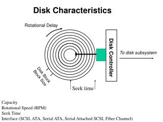
2 Overview of power converter control What does it take to control a type 1 power converter? State control: ON, OFF, RESET Diagnostics – record first fault in case of trip Current reference generation – requires timing and cycle user etc… Current measurement – DCCT Current regulation – Analogue or Digital Acquisition of current measurement Voltage measurement – Voltage divider Voltage regulation – Analogue or Digital Firing control Acquisition of voltage measurement Logging of signals in case of trip (post mortem) Generation of Alarms
2 Overview of power converter control Differences between existing control and FGC3 for the PSB converters
2 Overview of power converter control In summary, with the FGC3: Function generation and acquisition are moved from external systems into the FGC. Timing and event reception passes via the FGC gateway Current regulation is done digitally in software: ACAPULCOVoltage Source Vref Vload F(z) Iref DAC Iload Imeas ADC FGC3
2 Overview of power converter control FGC State Machine This state machine is used in the LHC power converters. It was extended to support cycling in the PS MPS and POPS. It is now used in the new SPS MUGEF software thatwill be installed during LS1. It supports non-cycling referencefunctions: IDLE, ARMED, RUNNING. It supports cycling referencefunctions: TO_CYCLING,CYCLING, POLARITY. The state machine combinesconverter states (OFF,STARTING, STOPPING, …)and reference generation states (IDLE, ARMED, RUNNING, CYCLING). Not all transitions are used in allcases. ON_STANDBY can have differentbehaviours according to the type of converter.
2 Overview of power converter control ON_STANDBY State The ON_STANDBY state in the LHC was required to lock the current reference at the minimum value for the converter. In the PS complex, ON_STANDBY normallyblocks the converter firing resultingin ZERO current. In some cases it may also openthe circuit to remove the magnet’s inductance from influencing other coupledmagnets. In other cases it may groundthe circuit. This will be configurable with the FGC3so the same software class will be able to support all these ON_STANDBY behaviours.
2 Overview of power converter control SLOW_ABORT State The SLOW_ABORT state was essential for the LHC where circuits can have a LOT of energy. It smoothly ramps down the current reference to theminimum value before switching off the converter. This protects the superconducting magnetsand also the converter’s circuit breaker from unnecessary openingsat high power. Although less essentialfor warm circuits it isalways a good policy to stop a converter using SLOW_ABOUT.
2 Overview of power converter control FLT_STOPPING State A FAULT is defined as a condition that must cause the converter to stop. If any fault is detected when the converter is running, then the state will change to FLT_STOPPINGand the converter will shut down. Once the power has beendisconnected and any stored energy has beendischarged the statecan then change to FLT_OFF.
2 Overview of power converter control FLT_OFF State If any fault is detected when the converter is not running, then the state will FAULT_OFF and it is NOT possible torestart the converter from this state. All FAULTS are LATCHED. To restart the converter the fault condition must be cleared AND the faultlatch must be RESET. This will allow the statetochange to OFF, fromwhere it is possible to start the converter.
2 Overview of power converter control Reference Generation Depending on the type and use of a power converter the reference can be: DC set-point controlled using a knob Pulsed current reference controlled using a knob Waveform reference from a GFAS controlled using the function editor Waveform reference from an FGC3 controlled using a function editor or knobs
2 Overview of power converter control Reference Generation in an FGC The FGC software includes a function generation library that supports ten different types of reference function:
2 Overview of power converter control Function Generation Library The PLEP function is special because it can be initialised with a non-zero gradient. This is useful because it is able to move the current reference for a power converter from any value to any other value while respecting all the converter limits. It can therefore be used to abort a running function. PLEP
2 Overview of power converter control Function Generation Library The PPPL reference was created for the CERN PS main magnet controls. The field is ramped up in stages with a series of linear plateaus defined parametrically using seven values. These specify a fast parabolic acceleration followed by a slow parabolic deceleration, then a fast parabolic deceleration and finally a linear section that is not necessarily constant. PPPL
2 Overview of power converter control Function Generation Library TABLE and SPLINE The same table of time versus reference can be used with linear interpolation (TABLE) or parabolic spline interpolation (SPLINE).
2 Overview of power converter control Function Generation Library LINEAR and CUBIC LINEAR and CUBIC trim functions are useful for small changes in the reference, especially when many circuits must change synchronously, since unlike the PLEP function, the duration for the change is an input parameter. CUBIC trims are essential for super-conducting circuits because they avoid discontinuities in the rate of change, which would generate voltage spikes.
2 Overview of power converter control Function Generation Library SINE, COSINE, SQUAREand STEPS COSINE has windowing enabled to provide a smooth start and end
2 Overview of power converter control Regulation Regulating current generally requires three nested loops: Current, Voltage, Firing. None, some or all of the loops may be digital (the others are analogue). Regulation may use feedback or feedforward. Power Iref Vref Fref PWM Switchingbridges Function generator Current loop Voltage loop Firing Filter V Bridge voltage measurement Filter current measurement V Magnet voltage measurement I Magnets Magnet current measurement DCCT
2 Overview of power converter control Questions If a fault condition is active: • Depending on the fault the converter can sometimes continue to operate • The converter must stop but can be restarted • The converter must stop and cannot be restarted Without the FGC3 the ACAPULCO power converter is: • A voltage source • A current source • None of the above
CERN Operator TrainingFGC3 for power converter controls in the PSB • Corrector dipole and multipole power converter renovation in the PSB • Overview of power converter control • History of the FGC project • Features of the FGC3 • FGC system architecture • Working Sets/Knobs and function editor via INCA • OASIS • Alarms • Post Mortem • Expert interfaces • Use of FGC3 for other converters in the future
3 History of the FGC project • One controller per converter (~700 in total). • MIL1553 fieldbus. • 6809 microprocessor, FLEX OS and Pascal. • Analogue current regulation. • Function Generator included: Current reference created using DAC.
3 History of the FGC project • FGC project started in 1997 by the same team that produced the LEP controls. • First requirement was to control the converters in the magnet test benches in SM18 in 1999. • Function Generator/Controller Version 1 (FGC1). • One controller per converter (40 in total). • WorldFIP fieldbus. • Four 6U boards. • M68HC16 µP + TMS320C32 DSP in C. • Digital current regulation. • Reused LEP control crates. • Retired in 2010.
3 History of the FGC project • For the LHC radiation tolerance measures were required (EDAC). • An evolution of the FGC1 became the Function Generator/Controller Version 2 (FGC2). • Industrial form factor (20TE x 6U x 160mm) with a protective metal cassette. • 2100 produced, 1800 installed
3 History of the FGC project • First requirement for FGC control in the PS complex: the upgrade of the PS MPS regulation. • The FGC2 was adaptable to support regulation of magnetic field by receiving the B-train with an extension card. • New software class written to support cycling with PPM properties. • Dedicated application – no support for Working sets/Knobs.
3 History of the FGC project • Control of POPS required a new digital link to the VME controller from Converteam. • A new interface card was created. • The PS MPS software class was upgraded to support the link with the POPS controls. • Support for publication added so software can work with Working set/Knobs and INCA, although it will probably continue to be controlled with dedicated application.
3 History of the FGC project • Function Generator/Controller Version 3 (FGC3). • Evolution of FGC2 – Smaller, Faster, Cheaper. • Not radiation tolerant. • 700+ will be installed by the end of LS2. • WorldFIP or 100Mbps Ethernet.
3 History of the FGC project Questions The main feature lacking in the FGC1 that was added in the FGC2 was: • Support for PPM operation • Error correction for the memory • Ethernet interface Compared to the FGC2 the FGC3 is: • The same size • Smaller • Larger
CERN Operator TrainingFGC3 for power converter controls in the PSB • Corrector dipole and multipole power converter renovation in the PSB • Overview of power converter control • History of the FGC project • Features of the FGC3 • FGC system architecture • Working Sets/Knobs and function editor via INCA • OASIS • Alarms • Post Mortem • Expert interfaces • Use of FGC3 for other converters in the future
4 Features of the FGC3 What is inside an FGC3? A mainboard with two daughter boards: Analogue interface Network interface
4 Features of the FGC3 WorldFIPinterface Analogue interface forType 1 converters Mainboard: MCU, DSP, Memories, Logic, digital I/O Ethernetinterface Analogue interface forType 2 converters
4 Features of the FGC3 Why two types of analogue interface? Type 1 converters need 3 (or 4) acquisition channels up to ~10 ksps to allow continuous regulation of the current: • Circuit current from DCCT A • Circuit current from DCCT B • Voltage across the load • Converter output filter capacitor current,if FGC3 regulates the voltage Type 2 converters need two “slow” and two “fast” channels: • Fast (500 ksps): Load current Load voltage • Slow (10 ksps): Charger current Capacitor voltage
4 Features of the FGC3 Internal architecture of FGC3 RAM RAM MCU FPGA DSP Network interface Flash RAM RAM Analog I/O ADCs DACs Non-volatile RAM Power converter Digital I/O
4 Features of the FGC3 FGC3 Processing: Floating point microcontroller (RX610 @ 100 MHz) Runs a tiny real-time operating system called NanOS @ 1 kHz Manages communications with the network Manages power converter state and diagnostics 2 MB internal Flash for programs and databases 128 KB fast internal RAM for variables 1 MB external static RAM for post mortem logging 512 KB external non-volatile RAM for function data Floating point DSP (TI C6727 @ 300 MHz) No operating system Interrupt driven at required rate (1 – 20 kHz) Acquisition from analogue interface Function generation Current regulation Voltage regulation if required 256 KB fast internal RAM for program and variables 64 MB external RAM for functions and logging
4 Features of the FGC3 FGC3 Hardwaresummary: Everything is reprogrammable over the network Lots of memory and processing power Could work in the non-radiation areas in the LHC using WorldFIP network Will use faster Ethernet network everywhere else Analogue interface can be chosen too adapt to the requirements • Two versions so far, but more could be designed if needed Costs about 1000 SF (compared to 2500SF for the FGC2 in 2003)
4 Features of the FGC3 FGC3 context For some small converters (e.g. ACAPULCO, MidiDiscap) the FGC3 will plug directly into the converter:This saves the cost of a dedicated crate, PSU and cabling. For larger converters there will be a “RegFGC3 crate” containing the FGC3 and the other control and interlock cards needed to safely manage the power components: FGC3 RegDSP STATE DIG ANA SCOPE PSU Cables to power part
4 Features of the FGC3 Questions The FGC3 design supports two type of analogue interface: • One works with the WorldFIP network and the other with Ethernet • One has 3 acquisition channels and the other has 4 • One has 2 fast channels and two slow channels and the other has 4 channels of the same speed The non-volatile RAM memory in the FGC3 is: • Linked to the MCU • Linked to the FPGA • Linked to the DSP • There is no non-volatile RAM memory in an FGC3
CERN Operator TrainingFGC3 for power converter controls in the PSB • Corrector dipole and multipole power converter renovation in the PSB • Overview of power converter control • History of the FGC project • Features of the FGC3 • FGC system architecture • Working Sets/Knobs and function editor via INCA • OASIS • Alarms • Post Mortem • Expert interfaces • Use of FGC3 for other converters in the future
5 FGC system architecture FGC2 Architecture in the LHC Sequencer EquipState Logging Expert applications LSA FGC web site Configuration database Alarm server FGC status server Post mortemserver FGC configuration manager Timing system FGC gateway x 73 WorldFIPfieldbus FGC2 +P.Conv FGC2 +P.Conv FGC2 +P.Conv FGC2 +P.Conv FGC2 +P.Conv FGC2 +P.Conv FGC2 +P.Conv FGC2 +P.Conv x 30
5 FGC system architecture FGC3 Architecture in the PSB Working Sets/Knobs OASIS Expert applications INCA FGC web site Configuration database Alarm server FGC status server Post mortemserver FGC configuration manager Timing system FGC gateway x 5 FGC_Ether FGC3 +P.Conv FGC3 +P.Conv FGC3 +P.Conv FGC3 +P.Conv FGC3 +P.Conv FGC3 +P.Conv FGC3 +P.Conv FGC3 +P.Conv x 64
5 FGC system architecture What is FGC_Ether? FGC_Ether = 100 Mbps Ethernet + 50 Hz sync Why Ethernet and why the 50 Hz sync? 2.5 Mbps WorldFIP has a limited throughput – adequatefor the slow cycles of the LHC but inadequate for the fast cycling PS complex machines. 100 Mbps Ethernet provides the increased bandwidth. In order to have a guaranteed synchronisation signal the FGC needs a50 Hz pulse from the timing receiver in the gateway. Does that mean a separate cable and connector in the FGC3?
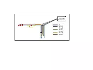
5 FGC system architecture What is FGC_Ether? FGC_Ether = 100 Mbps Ethernet + 50 Hz sync No! Copper Ethernet cable has 4 pairs but only 2 pairs are used for 100Mbps. An unused pair can send the 50 Hz sync pulse if we make a pulse injector to go between the Ethernet switch and the FGC3. In this way, only the backbone needs separate Ethernet and sync cables. The pulse injector costs 240SF (10SF/port) which is cheaper than a separate sync cable Machine timing TechNet One switch and one pulse injector are needed per 24 FGC3s FGCGateway CTRI Gigabit Ethernet 50 Hz sync Gigabit Ethernet Ethernet Switch Ethernet Switch 50 Hz sync 100 Mbps Ethernet and50 Hz sync share the same cable Pulse injector Pulse injector FGC3 FGC3 FGC3 FGC3 FGC3 FGC3 FGC3 FGC3 . . . 1 2 3 4 61 62 63 64