Download
1 / 29
300 likes | 427 Vues
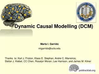
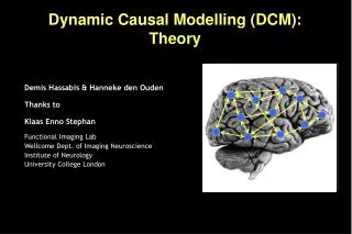
Dynamic Causal Modelling (DCM). Marta I. Garrido migarrido@ucla.edu. Thanks to: Karl J. Friston, Klaas E. Stephan, Andre C. Marreiros, Stefan J. Kiebel, CC Chen, Rosalyn Moran, Lee Harrison, and James M. Kilner. Motivation. Functional specialisation. Functional integration.

E N D
Dynamic Causal Modelling (DCM) Marta I. Garrido migarrido@ucla.edu Thanks to: Karl J. Friston, Klaas E. Stephan, Andre C. Marreiros, Stefan J. Kiebel, CC Chen, Rosalyn Moran, Lee Harrison, and James M. Kilner
Motivation Functional specialisation Functional integration Varela et al. 2001, Nature Rev Neuroscience Interactions between distant regions Analysis of regionally specific effects • Effective Connectivity • The influence one neuronal system exerts over another • Requires a mechanism or a generative model of measured brain responses • Functional Connectivity • Correlations between activity in spatially remote regions • independent of how the dependencies are caused MODEL-FREE MODEL-DRIVEN
Outline DCM: the neuronal and the hemodynamic models Estimation and Bayesian inference Application: Attention to motion in the visual system Extensions for fMRI and EEG data
z λ y I. DCM: the basic idea The aim of DCM is to estimate and make inferences about the coupling among brain areas, and how that coupling is influences by changes in the experimental contex. (Friston et al. 2003, Neuroimage) • Using a bilinear state equation, a cognitive system is modelled at its underlying neuronal level (which is not directly accessible for fMRI). • The modelled neuronal dynamics (z) is transformed into area-specific BOLD signals (y) by a hemodynamic forward model (λ).
direct inputs modulatory input u2(t) driving inputu1(t) t t I. Conceptual overview y y BOLD y λ y hemodynamic model b23 a12 activity z2(t) activity z3(t) activity z1(t) z integration c1 Neuronal state equation intrinsic connectivity modulation of connectivity direct inputs Stephan & Friston 2007, Handbook of Connectivity
I. The hemodynamic “Balloon” model 5 hemodynamic parameters: Buxton et al. 1998 Mandeville et al. 1999 Friston et al. 2000, NeuroImage
State vector • Changes with time • Rate of change of state vector • Interactions between elements • External inputs, u • System parameters I. Elements of a dynamic neuronal system
I. Connectivity parameters = rate constants Generic solution to the ODEs in DCM: Decay function Coupling parameter describes the speed ofthe exponential decay Half-life:
z2 sa21t z1 I. Linear dynamics: 2 nodes z1 z2
I. Neurodynamics: 2 nodes with input u1 u1 u2 Stimulus function z1 z1 z2 z2 activity in z2 is coupled to z1 via coefficient a21
I. Neurodynamics: modulatory effect u1 u1 u2 u2 z1 z1 z2 z2 index, not squared modulatory input u2 activity through the coupling a21
I. Neurodynamics: reciprocal connections u1 u1 u2 u2 z1 z1 z2 z2 reciprocal connection disclosed by u2
I. Hemodynamics blue:neuronal activity red: bold response u1 BOLD (no noise) u2 h1 z1 h2 z2 h(u,θ) represents the BOLD response (balloon model) to input
I. Hemodynamics (with noise) blue:neuronal activity red: bold response u1 BOLD noise added u2 y1 z1 y2 z2 y represents simulated observation of BOLD response, i.e. includes noise
I. Bilinear state equation in DCM for fMRI context-dependent state vector induced connectivity state changes driving inputs latent connectivity n regions m drv inputs m modulatory inputs
lpost-1 lp-1 ld-1 Mp Mpost Md II. Estimation: Bayesian framework • Models of • Hemodynamics in a single region • Neuronal interactions • Constraints on • Hemodynamic parameters • Connections prior likelihood term probability that a parameter (or contrast of parameters cT ηθ|y) is above a chosen threshold γ posterior Bayesian estimation ηθ|y
II. Parameter estimation stimulus function u neuronal state equation • Specify model (neuronal and hemodynamic level) • Make it an observation model by adding measurement errore and confounds X (e.g. drift). • Bayesian parameter estimation using expectation-maximization. • Result:(Normal) posterior parameter distributions, given by mean ηθ|y and Covariance Cθ|y. parameters hidden states state equation ηθ|y modeled BOLD response observation model
Pitt & Miyung 2002, TICS II. Bayesian model comparison Given competing hypotheses, which model is the best?
Model 2:attentional modulationof SPC→V5 SPC V1 V5 Attention Photic 0.55 0.86 0.75 1.42 0.89 -0.02 0.56 Motion III. Application: Attention to motion in the visual system Model 1:attentional modulationof V1→V5 Photic SPC 0.85 0.70 0.84 1.36 V1 -0.02 0.57 V5 Motion 0.23 Attention Büchel & Friston
IV. Extensions: Slice timing model • potential timing problem in DCM: • temporal shift between regional time series because of multi-slice acquisition 2 slice acquisition 1 visualinput • Solution: • Modelling of (known) slice timing of each area. • Slice timing extension now allows for any slice timing differences • Long TRs (> 2 sec) no longer a limitation. • Kiebel et al. 2007, Neuroimage
IV. Extensions: Two-state model Single-state DCM Two-state DCM input é ù é ù L EE EI E A - - x A A e e e 0 11 11 1 N 1 ê ú ê ú IE II I - x A A e e 0 0 ê ú ê ú 11 11 1 ê ú ê ú M = = M O M A x ( t ) ê ú ê ú EE EI E A - - x A A ê ú e 0 e e ê ú N 1 NN NN N ê ú ê ú L IE II I - x A A 0 0 e e ë û ë û NN NN N Extrinsic (between-region) coupling Intrinsic (within-region) coupling • Marreiros et al. 2008, Neuroimage
non-linear DCM modulation driving input IV. Extensions: Nonlinear DCM bilinear DCM driving input modulation Two-dimensional Taylor series (around x0=0, u0=0): Bilinear state equation: Nonlinear state equation: Here DCM can model activity-dependent changes in connectivity; how connections are enabled or gated by activity in one or more areas. • Stephan et al. 2008, Neuroimage
IV. Extensions: DCM for ERPs Jansen and Rit 1995 David et al. 2006, Kiebel et al. 2006, Neuroimage
IFG IFG FB F STG STG STG STG deviants standards A1 A1 A1 A1 input input Forward Backward Lateral IV. Extensions: DCM for ERPs a b c with backward connections and without rIFG lA1 rA1 rSTG lSTG Garrido et al. 2007, PNAS
IV. Extensions: DCM for ERPs a b Grand mean ERPs 128 EEG electrodes c ERP oddball model inversion from 0 to t where t = 120:10:400 ms for F and FB Garrido et al. 2007, PNAS
IV. Extensions: DCM for ERPs Garrido et al. 2008, Neuroimage
The DCM cycle Hypotheses abouta neural system Statistical test on parameters of optimal model DCMs specification models the system Design a study to investigatethat system Bayesian modelselection of optimal DCM Parameter estimationfor all DCMs considered Data acquisition Extraction of time seriesfrom SPMs
State space Model Model inversion using Expectation-Maximization DCM roadmap Neuronal dynamics Hemodynamics Priors Posterior densities of parameters fMRI data Model comparison
Dynamic Causal Modelling (DCM) Marta I. Garrido migarrido@ucla.edu Thanks to: Karl J. Friston, Klaas E. Stephan, Andre C. Marreiros, Stefan J. Kiebel, CC Chen, Rosalyn Moran, Lee Harrison, and James M. Kilner