Download
1 / 41
410 likes | 613 Vues
GEOGG141 / GEOG3051 Principles & Practice of Remote Sensing (PPRS) RADAR II: Interferometry. Dr. Mathias (Mat) Disney UCL Geography Office: 113, Pearson Building Tel: 7670 0592 1 Email: mdisney@ucl.geog.ac.uk www.geog.ucl.ac.uk /~ mdisney. Definitions and terms.

E N D
GEOGG141 / GEOG3051Principles & Practice of Remote Sensing (PPRS) RADAR II: Interferometry Dr. Mathias (Mat) Disney UCL Geography Office: 113, Pearson Building Tel: 7670 05921 Email: mdisney@ucl.geog.ac.uk www.geog.ucl.ac.uk/~mdisney
Definitions and terms • IfSAR or InSAR – Interferometric SAR • DifSAR – Differential Interferometric SAR References • http://www.esa.int/esapub/tm/tm19/TM-19_ptA.pdf • http://www.gi.alaska.edu/~rgens/teaching/asf_seminar/intro_insar.pdf • http://www.jpl.nasa.gov/srtm/missionoverview.html • http://www.jpl.nasa.gov/srtm/instrumentinterfmore.html • http://southport.jpl.nasa.gov/scienceapps/dixon/report2.html • http://southport.jpl.nasa.gov/nrc/index.html - good info but dated • http://www-radar.jpl.nasa.gov/insar4crust/ • http://earth.esa.int/workshops/ers97/program-details/speeches/rocca-et-al/ • http://earth.esa.int/landtraining07/D1LB5-1-Rocca.pdf
INSAR • Interferometry is a technique for combining coherent measurements • Essentially looks at the difference in phase between two coherent measurements and deduces distance information from this • SAR interferometry needs at least (i) two radars or (ii) radar imaging from two places
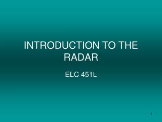
Principle of SAR Interferometry A1 and A2 are known Positions determined From satellite orbit or GPS/INS The range difference is determined from , the measured phase difference.
Though ERS images are usually presented as amplitude (e.g. PRI images), the radar measurements are actually complex (e.g. SLC). • Strictly speaking we have two images, which encode amplitude and phase • To derive an amplitude image, we throw away the phase information • The phase image on its own may have no useful information • To derive an interferogram, we take the difference of two phase images
0 2p 4p 6p... INSAR – phase difference? • phase is a measure of “how far the wave has travelled” • The relationship between phase and distance is (in general) f = 2pd / l • i.e. if we have travelled by a wavelength (d=l) then the phase has changed by 2p.
INSAR • Interferometry depends on the fact that we are using waves (electric fields). • Two waves can interact to give brighter light (constructive interference) but also darker radiation patterns (destructive interference) darkness. + = CONSTRUCTIVE DESTRUCTIVE + =
INSAR • Phase information is effectively random noise in a single SAR image (because the phases are randomised by all the scattering on the Earth’s surface) • However, if we view from another position very close to the first, then the differences in phase tell us about the differences in distance. • Then it is just a matter of geometry...
Difference between the two path lengths related to the difference in phase of the received electric fields,Interferometry used to generate two sorts of products - a coherence image, and a phase image (called the interferogram)
Interferogram For generating an interferogram, two co-registered SAR images covering the same area are multiplied in a complex fashion. The result of this complex multiplication is the average of the two SAR images and the difference of their corresponding phase values. The interference pattern, also called FRINGE, is stored in a range of [ -π , π ].Interferograms show differences in phase. This phase difference is the result of a path length difference that can be caused by elevation differences, motion, or deformation. Hence, we can use interferograms to derive accurate elevation maps, monitor small motions, and detect tiny deformations.
Registration The phase difference can only be determined from two images taken from slightly different positions – both images are therefore almost identical The phase difference is determined at pixel level on the two images, therefore pixels must correspond. Registration is done by standard correlation and transformation techniques
Shuttle Radar Topography Mission SRTM http://rst.gsfc.nasa.gov/Sect11/Sect11_10.html
INSAR • Note that with two images, we can create two products:- • An entire image of the phase information is known as the interferogram • An image of the coherence (i.e. the correlation between the two images) • coherence near 1 means the phase information is reliable (and the images have high degree of correlation) • coherence < ~ 0.3 means the images have low correlation (noisy). In this case, the phase information is probably not useful.
Coherence The coherence is a measure of the correlation of the phase information of two corresponding signals and varies in the range of 0 to 1. The degree of coherence can be used as a quality measure because it significantly influences the accuracy of phase differences and height measurements. Bright areas indicate regions of high coherence, whereas dark areas represent low coherence regions.
Coherence There are several factors decreasing the coherence. In approximate order: • Local slope (steep slopes lead to low coherence) • Properties of the surface being imaged (vegetated or moving surfaces have low coherence). • Time difference between the passes in an interferogram (long time difference lead to low coherence) • The baseline (large baselines lead to low coherence) • Technical details of the generation of the interferogram (poor co-registration or resampling leads to low coherence) • Atmosphere
Phase unwrapping Phase can only be detected between - and -π, π but the actual phase shift between two waves is often more than this. Phase unwrapping is the process of reconstructing the original phase shift from this "wrapped" representation. It consists of adding or subtracting multiples of 2 in the appropriate places to make the phase image as smooth as possible. To convert interferometric phase into elevation, you must perform phase unwrapping.
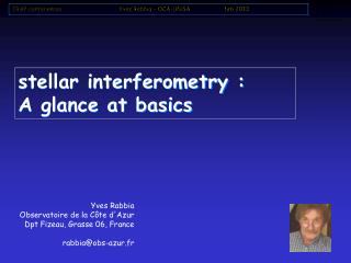
MountVesuvius ERS SAR
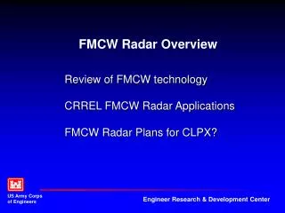
Mt Etna interferogram X-band (SIR-C/X-SAR mission)
Data acquisition • Configuration can come from: Repeat pass • ERS-1, 2, Radarsat, ENVISAT ASAR, ALOS PALSAR Single Pass • Shuttle Radar Topography Mission SRTM • Aircraft
Sources of IfSARdata - newer • ASAR on ENVISAT (2002-?) • Cosmo-Skymed – 2007/8 • http://www.telespazio.it/cosmo.html • TerraSAR-X (2007-), TANDEM-X (2010-) • http://www.infoterra.de/tandem-x-satellite • RADARSAT 2 (2007- ) • http://www.asc-csa.gc.ca/eng/satellites/radarsat2/ • KOMPSAT-5 X-band, 2012? • Smotr (Russia) – TBD?
Problems • Physical changes between two acquisitions cause loss of coherence (eg rainfall, wind, field ploughing, vegetation growth) • TEMPORAL DECOHERENCE (degradation in the quality of the phase measurement) • Differential Interferometry - generate two interferograms and then take the difference
ERS Tandem Mission • ERS-1 and ERS-2 in same orbit with a repeat cycle of 35 days • ERS-2 35 minutes behind ERS-1 – this gives coincidence of ground track after 24 hours
SRTM - http://semana2.terra.com.co/imagesSemana/documentos/SRTM_Eos_vidamodmapanasa.doc The Level-2 Terrain Height Data Sets contain the digital topography data processed from the C-Band data collected during the mission. For data between the equator to 50 degrees latitude, the postings are spaced at 1" (one arcsecond) latitude by 1" longitude. At the equator, these are spacings of approximately 30 meters by 30 meters. The absolute horizontal accuracy (90% Circular Error) is 20 meters. The absolute vertical accuracy (90% Linear Error) is 16 meters.
Processing of SRTM data • Measurement of base length is critical • SRTM mast not stable • Therefore movement of outboard antenna must be monitored and correction made • Unexpected movement of the shuttle can cause problems
Accuracy of IfSAR • Theoretical accuracy very high – sub wave length • Dependent on • Base length • Terrain • Atmosphere • Coherence
Global SRTM AccuracyVerification Data Sets • Kinematic GPS: Data collected by NIMA for SRTM validation using kinematic GPS data processing (estimated accuracy: <50 cm). The total number of globally distributed KGPS points is: 20,150,000 • DTED-2: 21 DTED level 2 patches. Height posting identical to SRTM. Height accuracy similar to SRTM. • DEM Patches: 50 small patches similar to DTED-2 prior to editing in accuracy. • Ground Control Points: • 50,000 NIMA land GCPs with varying height accuracy. • Millions of ocean GCP’s from mean sea surface and tidal model with an accuracy better than 50 cm. • GeoSAR Data: meter level accuracy and geolocation for X-band interferometer data.
Global SRTM AccuracyGelocation Error from KGPS Tracks • Geolocation errors can be estimated by matching the KGPS tracks with roads identifiable in the radar imagery • In addition, geolocation can also be estimated by matching the road KGPS topography with the SRTM topography. • The accuracy of the estimate depends on scene contrast, road geometry, and topography. • Africa 90% geolocation error: 11.9 m • Australia 90% geolocation error: 7.2 m • Eurasia 90% geolocation error: 8.8 m • North America 90% geolocation error: 12.6 m • South America 90% geolocation error: 9.0 m
Aerial photography Comparison of IfSAR with Lidar DTM
The LANDMAP project • Generation of IfSAR DEM from ERS data • Geocoding of ERS images • QA of strips • Mosaic of strips • Geocoding and mosaicing of other image datasets http://www.landmap.ac.uk/
Differential IfSAR Movement of objects creates parallax Two images from different positions parallax from bottom parallax from top Two images from same position at different times: object moves, parallax created
Differential IfSAR • If two images taken from identical positions, then any parallax will come from movement of object. But… • Sensor not in the same position nor orientation • Baseline, viewing angle and attitude can be determined using ground control. • Cannot resolve difference in plan and elevation movement unless sensor vertically above
Requirements • Images from near nadir • DEM to correct off nadir effects • Ground control to determine orientation • Fairly constant movement so that measurements can be averaged • Sub pixel correlation
Subsidence from Differential IfSAR Examples from NPA Group http://www.npagroup.com/index.htm