Download
1 / 17
170 likes | 438 Vues
Nexus 1-8 Loop (XP95) Analogue Addressable Control Panels. From 1 to 8 loops Powerful processing and extensive panel and loop I/O capability Fully compatible with all XP95 devices User-friendly controls and a clear, unambiguous screen Alarm threshold adjustments by device

E N D
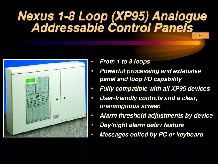
Nexus 1-8 Loop (XP95) Analogue Addressable Control Panels • From 1 to 8 loops • Powerful processing and extensive panel and loop I/O capability • Fully compatible with all XP95 devices • User-friendly controls and a clear, unambiguous screen • Alarm threshold adjustments by device • Day/night alarm delay feature • Messages edited by PC or keyboard
Nexus 1-8 Loop (XP95) Analogue Addressable Control Panels • Multiple, fully functional panel displays • Radio pager facility • Easy to use, Windows-based PC software package • Fully networkable with graphics package, network repeaters & other Nexus panels • Designed to meet BS5839 Part 4
Panel Enhancements Up to 31 8-way panel enhancement boards may be added. Two types are available: 1) fully-programmable inputs and relay outputs 2) fully-programmable inputs and alarm outputs Remote Inputs for Silence Alarms, Reset, Evacuate, Class Change, Fault, Buzzer Silence. Fully programmable network comprising other Nexus multi-loop panels, graphics systems and network repeaters. A wide variety of loop devices are supported, including XP95 detectors, call points, loop sounders, outstations and intrinsically safe devices. Individual panels and Nexus panel networks are programmable via Windows PC package. Up to 13 remote panel displays, providing full user & engineer facilities may be connected via RS485 cable.
Cabinet Options Surface Cabinets Cabinet colour reference is: RAL 7035 textured (Light Grey) All cabinets are manufactured from sheet steel and finished in satin texture epoxy powder stove paint. Semi-Flush Cabinets The semi-flush bezel locates to the rear of the bevelled edge of the back box, leaving the bevelled edge and door raised out from the wall. It is finished in the same colour as the back box and is fitted by means of pinch bolts, thus avoiding the need to drill the cabinet. Fully Flush Cabinet (Illustrated) Custom-made to a high quality, full-flush bezels are available in brass, stainless steel, or painted. This option is achieved by fixing a flat bezel assembly to the standard back box, replacing the standard door. The panel comes with assembly already fitted but may be supplied for later on-site fitting (this may be a little time-consuming). For details of panel dimensions see Application Guide.
Mechanical Assembly Motherboard holds Konex network card and 2 loop cards. Motherboard and power supply located on removable chassis to assist cabinet installation. Loop extension motherboard - this chassis is located in the right hand section of the enclosure. Display assembly located on removable door. A1535 programmable relay board / A1536 programmable alarm board - a maximum of 2 boards may be housed internally and up to 29 externally. Zone LEDs and option printer are located on display board. Space for internal 12Ah battery set.
User Controls The backlit LCD display gives information of loop, device and zone number, device type and event condition, together with a user-definable text description. The text descriptions give the user clear, single-operation functional controls. The engineer accesses panel configuration functions using the numerical designations. The menu structure on the LCD display guides the engineer through the different set-up facilities. System LED indications are provided in addition to the LCD display.
Typical LCD Illustration The device types which may be indicated are as follows: SOU - Loop sounder/sounder circuit controller O/S - Input/Output device ION - Ionisation smoke sensor MON - Monitor (zone monitor, control monitor) OPT - Optical smoke sensor HEAT - Heat sensor BGU - Call point or call point monitor
Display /Repeater PCB (A1575) Viewed from Inside Cabinet Comms link to the main panel motherboard. Power supply fault input when used as a repeater with a local power supply unit. LCD display. System Eprom. S13 Display number Address switch (Node Address Switch) 16 way ribbon connector to the zone board. 16 way ribbon connector to the printer interface. DC power in.
Zone Indications The Nexus 1-8 loop panel provides 64 fully programmable zone LEDs. The zone identification label may be inserted from inside the cabinet
Engineer Facilities The fault LEDs, fuses and DIL switch are easily accessible for the engineer when the user display board has been removed.
Power Supply The fault LEDs, fuses and DIL switch are easily accessible for the engineer when the user display board has been removed. Decoupling link. 230V AC supply. Test lamp switch. Battery supply fuse - 6.3 Amps. These LED indications give the engineer more details of the fault when the “Power Supply Fault” message has appeared on the panel display.
Printer Hinged access to allow easy ribbon change. This good quality printer uses a reliable Epson mechanism. Engineer’s printer test button. Open access to feed paper through mechanism. This button advances the paper. Designed for easy replacement of the paper roll onto the carrier.
A1535 8 Way Relay Board RS485 comms from panel motherboard. Engineer’s DIL switches to set board address, enable O/C or S/C inputs and disable inputs/outputs. 8 inputs may be normally open or normally closed and will register as fire or non-fire on the panel as configured. Inputs are fully programmable via the panel or PC cause/effect. 8 x 1Amp changeover relay outputs may be fully programmed via the panel or PC cause/effect programme. Engineer’s links to disable functions for set-up or maintenance purposes. 24V DC power.
A1536 8 Way Alarm Board Engineer’s DIL switches to set board address, disable inputs and outputs, test LEDs and test alarms. Engineer’s DIL switches to isolate alarm outputs individually. RS485 comms from panel motherboard. 8 x 1Amp two-stage alarm outputs may be fully programmed via the panel or PC cause/effect. 8 normally open inputs which will register as fire or non-fire on the panel as configured. Inputs are fully programmable via panel or PC cause/effect. Alarm Fault LEDs. Test alarms when switched to 0V. Engineer’s buzzer disable link for set-up or maintenance purposes. 24V DC power.
Windows-based PC Programming A Windows-based PC programming package is available for panel set up, zones, text, local and network cause/effect.
Typical Radio Pager Configuration The radio pager system, when connected to the control panel, can be used to transmit both text and numeric messages direct to pocket pagers. Pagers will display Fire / Fault conditions including Sensor location text. Up to 9,999 pagers can be connected to system. Connection to panel printer port. Transmitter Interface board Opto isolator
XP95 Test Tool The XP95 Test Tool is an engineer’s tool to assist with commissioning and fault finding on XP95 loop systems. Loop configurations and the status of each device may be interrogated, device LEDs may be turned on/off. The test tool may be connected to an entire loop without the panel connected or connected to individual devices around the circuit. Alpha-numeric LCD display. Sockets for flying leads to connect to loop and/or individual XP95 devices. Engineer’s keypad. Battery charger socket. On/off switch and LED indication.