Download

1 / 67
670 likes | 841 Vues
RECYCLER BPM SYSTEM UPGRADE,. BPM TEST STATUS. & FUTURE PLANS. Brajesh Choudhary & Martin Hu. Thanks to:. Jim Crisp, Peter Prieto, Duane Voy, Tom Meyer & Craig McClure for hardware and software support. Special thanks to:.

E N D
RECYCLER BPM SYSTEM UPGRADE, BPM TEST STATUS & FUTURE PLANS Brajesh Choudhary & Martin Hu
Thanks to: Jim Crisp, Peter Prieto, Duane Voy, Tom Meyer & Craig McClure for hardware and software support. Special thanks to: Bill Foster & Ming-Jen Yang for ideas and discussion. To Consolato Gattuso for his ever helpful presence. Thanks also to: Mark Ross, Jim Sebek,Till Straumann and Douglas McCormick of SLAC for ideas.
BASICS Recycler Ring is an 8 GeV storage ring constructed using permanent magnets. It is expected to increase the Tevatron collider luminosity in two ways: • Maintain high pbar production rate in the Accumulator by periodically sending the pbar stack to the Recycler, and • By recycling the left over pbars from the Tevatron to the Recycler and further cooling it, before injecting again in the Tevatron.
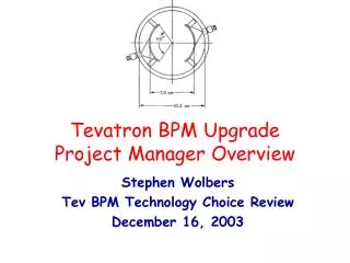
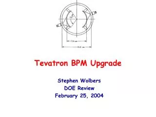
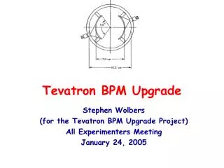
WHAT IS A BPM? Beam Position Monitor: The conventional beam position monitor has a pair of electrodes (or 2 pairs, if 2 beam position coordinates are to be measured) on which signals are induced. The ratio of the amplitudes of the induced signals at the carrier frequency, either the beam-bunching frequency or a harmonic, is uniquely related to the beam position. Recycler BPM system: The present recycler BPM system consists of 30cm long elliptical split-plate detectors matching the Recycler pipe shape, with axis dimensions of 9.6cm by 4.4cm. In some of the straight sections the Recycler uses round BPM’s that have a 10cm aperture.
RECYCLER BPMs End View Top View Split tube BPM Design Pictures - Courtesy Jim Crisp
NEED FOR GOOD BPMs In the Recycler, the BPM system is used for orbit measurement, as well as for ion clearing purpose. For this reason, initially it was decided to have 2 BPM’s per half cell or a total of 414 BPM’s for the 3320 meter ring. The associated injection and extraction beam lines together have an additional 28 BPM’s. Why do we need a precision BPM system: • To measure “Injection oscillation” or “Orbit closure”. • To have a proper “Global orbit control” or to minimize the feed down effect, and • To have proper turn-by-turn (TBT) lattice measurement.
PRESENT BPM SYSTEM - A BRIEF OVERVIEW In the present BPM system, the BPM electrodes reside in a vacuum inside the Recycler beampipe. The capacitance of the BPM electrodes and inductors at the input of the first pre-amp forms a resonant circuit at 7.5 MHz with a ‘Q’ of about 6. A second amplification stage with another 7.5 MHz resonant circuit (‘Q’~15) is used to drive the long cable runs from the tunnel to the service buildings. In the service buildings, the signals are transformed from differential to single-ended and routed to the log amplifier modules which provides the log of A/B to the digitizers and the ACNET front-end. The output of the log amplifier is a sample and hold signal triggered relative to beam revolution markers.
STATUS OF THE CURRENT BPM SYSTEM Inadequacies of the present BPM system: • Frequency capability – Does not work at all required frequencies. Tuned to the third harmonic (a single frequency of 7.5 MHz) and is very sensitive to RF parameters. Need to work at 89 KHz, 2.5 MHz & 7.5MHz. • Logarithmic Amplifiers – Non-conformity of log amps leads to sampling time error. Log amps are designed to measure steady state signal, and are not very reliable with transient signal. • Channel Coupling – Coupling between BPM plates degrades the signal. • Reliability Issues – for example, switch failure due to perceived radiation damage.
USER's OBSERVATIONS ABOUT THE PRESENT BPM SYSTEM • The present system is noisy (large rms). • Poor transient (first turn) measurement of the beam position due to log non-conformity error inherent in the log amp modules. • Poor consistency of measurement of the same beam. • Uncertainty in offset or the physical center of the BPM. • Uncertainty in the reported absolute position. • Inconsistencies in reported relative position (orbit difference). • The measured relative displacements fall short of the MAD model prediction. • Poor measurement reproducibility on longer time scale (hours, days etc.).
WHY AN UPGRADE? The motivation for upgrade has been necessitated to overcome the inherent limitations as well as performance shortfalls of the current system. The Digital BPM has the following characteristics (from Peter Preito’s note & Jim Crisp): • The new system uses a low pass preamp filter. • The BPM, pre-amp and the cable forms a band pass circuit. • Preamp input R and Cplate+Ccable set the corner frequency of 10MHz. • Reduces coupling at 2.5MHz and 7.5MHz by reducing the preamp input impedance.
UPGRADE PROPOSAL • Replace log amps with commercial digital receivers EchoteK ECDR-GC814 board (in the service building). • Modify preamps in the tunnel to work at 89 KHz, 2.5 MHz & 7.5 MHz – make the system more flexible. • No. 2 requires work on VME crates and cables (in service buildings). • New modified software to read out digital down converter. • Implement MDAT decoder software. MDAT is a communication system that transmits a variety of machine related information. In the case of the Recycler, MDAT provides the facility to track barrier bucket location based upon data provided by the Recycler Ring Low Level RF.
FUNCTIONAL SPECIFICATIONS AND REQUIREMENTS Alignment Requirements: The required relative alignment of the detector is defined in the “alignment reference table”. The position of the BPM’s also have a specific offset from the center line of adjacent magnets depending on the type of gradient magnets at the given location. Tolerance for BPM Value Transverse Offset 0.25mm Relative Roll 5 mrad
FUNCTIONAL SPECIFICATIONS AND REQUIREMENTS • RECYCLER OPERATIONAL MODE (for Protons and Pbars): • 2.5 MHz – In this mode of operation the MI completes a bucket to bucket transfer of 4 coalesced (2.5MHz) bunches spaced 21, 53MHz buckets apart into the Recycler. The Recycler captures the beam in the 2.5MHz buckets spaced 21, 53 MHz buckets apart. • 7.5 MHz – Same as above but in this case the Recycler also plays out a 7.5MHz waveform on top of the 2.5MHz waveform. • 89 KHz debunched beam in the barrier buckets – barrier buckets in the Recycler are typically 40 buckets wide (53 MHz buckets) and can have separations from 20 to 504 buckets with varying intensity listed in the dynamic range.
FUNCTIONAL SPECIFICATIONS AND REQUIREMENTS System Performance Requirements: The BPM system should be able to measure the beam position with these RF’s: • 4 x 2.5 MHz Bunches (st = 25 to 50 nsec) • 12 x 7.5 MHz Bunches (st = 6 to 12 nsec) • Barrier buckets with de-bunched beam (89KHz)
FUNCTIONAL SPECIFICATIONS AND REQUIREMENTS • Dynamic Range - We need to be able to measure: • 1. From 0.3E10/bunch (1.2E10 total) to 7.5E10/bunch (30E10 total) particles for all 2.5MHz transfers. • From 0.1E10/bunch (1.2E10 total) to 2.0E10/bunch (24E10 total) particles for all 7.5MHz transfers. • From 1E10 to 400E10 particles for 89 KHz stored beam.
FUNCTIONAL SPECIFICATIONS AND REQUIREMENTS SPECIFIC MEASUREMENTS: • For less than 1E10 particles or greater than 10mm amplitude, 1.5mm rms in absolute position and 0.5mm rms resolution reproducibility - subsequent measurements of the same beam. • For greater than 10E10 particles and less than 10mm amplitude 0.5mm rms in absolute position and 0.15mm rms resolution reproducibility – subsequent measurement of the same beam. • Ability to close the Recycler injection orbit to the closed orbit to less than 250 microns. • Day to day stability to the level of 1 and 2.
FUNCTIONAL SPECIFICATIONS AND REQUIREMENTS SOFTWARE REQUIREMENTS: The BPM system must provide real time data acquisition modes, operation mode coordination, and data scaling and access methods. The real-time component of this package implements the following operational modes: • Flash Mode: Single turn position of beam orbit around the ring. One need to be able to measure the first turn beam orbit in the Recycler after injection to the same accuracy as later orbits. • Background Flash Mode: Flash data taken at 200Hz. • Closed Orbit Mode: Average of up to 128 background flashes. • Turn-by-Turn Mode: Flash data for up to 1024 consecutive turns.
TESTS OF DDC BPM’s • Three bump scale and linearity measurement and comparison with the model. • BPM noise measurement. • Beam position stability over long time (hour, day) for stored beam. • Beam position stability for repeat injection (proper orbit closure). • Beam Position vs. Beam Intensity measurement. • Beam Position vs. Injection Phase Error measurement. • Position of 2.5 MHz beam with a large amount of debunched beam nearby. • Position of debunched beam in the barrier bucket, leading and trailing edges. • System sensitivity over a large range of RF voltage (Beam Position vs. Bunch Width measurement without barrier bucket). • Test the transient response besides moving phase and TBT measurement.
STATUS OF DDC CHANNEL TEST We have acquired two EchoTek ECDR-GC814 digital receiver board. Each DDC board replaces four channels of the BPM. Both the board has been tested on the test stand with 2.5 MHz test pulse. The following 8 channels of old BPM system (with log amps) were replaced with the DDC board: • HP426, HP428, VP427, & VP429 • HP604, HP606, VP603, & VP605 Several of the measurements described earlier (nos. 1, 2, 3, 4, 5, 6 & 9) were made with these 8 channels. Studies described in nos. 7, 8 and 10 are in progress.
VISUAL COMPARISON OF OLD BPM W/LOGAMP & NEW BPM W/DDC Fast Time Plot with IBEAM=1.25E11 6mm HP226 Present Log amps 12mm New BPM’s w/DDC looks much quieter compared to the old BPM system. VP429 w/DDC HP428 w/DDC VP427 w/DDC -6mm
SATURATION OF PREAMPS IN THE NEW BPM SYSTEM Six different injections with IBEAM~2.4E11. Fast time plot for each data set for about 12mts. No correction elements were moved. Beam position “as recorded” changed. Saturation of BPM preamps. To be fixed when we get the tunnel access. (FIXED) HP428 20mm VP427 VP429 HP426 3:43AM 4:52AM
SATURATION OF PREAMPS IN THE NEW BPM SYSTEM 6 different injections. 3 w/IBEAM~2.4E11. 3 w/IBEAM~1.25E11. Beam position is very stable for IBEAM~1.25E11. Variation in positions could be seen for IBEAM~2.4E11. Saturation effect. Each data set is for ~12 mts. The thickness of the trace is not noise. These are 29 ramps. IBEAM = 2.4E11 1.25E11 HP428 1.25E11 VP427 20mm VP429 HP426 16:52 18:10
DISPERSION MEASUREMENT NOMINAL FREQ = 52810196 HP426 VP427 RMS=18mm RMS=13mm IBEAM = 1.25E11 HP428 VP429 RMS=27mm RMS=18mm
DISPERSION MEASUREMENT Nominal Frequency = 52810196 Changed Frequency = 52810696 Change by +500
DISPERSION MEASUREMENT NOMINAL FREQ + 500 = 52810696 VP427 HP426 RMS=8mm RMS=12mm IBEAM = 1.10E11 HP428 VP429 RMS=15mm RMS=12mm
DISPERSION MEASUREMENT Nominal Frequency = 52810196 Changed Frequency = 52809696 Change by -500
DISPERSION MEASUREMENT NOMINAL FREQ - 500 = 52809696 VP427 HP426 RMS=12mm RMS=22mm IBEAM = 0.95E11 HP428 VP429 RMS=25mm RMS=18mm
DISPERSION MEASUREMENT THE VERTICALS SHOWED ALMOST NO CHANGE
RF VOLTAGE vs. STABILITY RF Voltage lowered by 50%. FARBG2 changed from 0.8 to about 0.4
RF VOLTAGE vs. STABILITY. VOLTAGE LOWERED BY 50%. HP426 VP427 RMS=16mm RMS=18mm IBEAM = 2E11 HP428 VP429 RMS=34mm RMS=23mm No difference in data quality.
RF VOLTAGE vs. STABILITY. VOLTAGE LOWERED BY 50% FARBG2 changed from 0.8 to 0.4. No difference in data quality. Some beam can be visibly seen outside the RF buckets on MI channel 17. VP427 HP426 VP429 HP428
RF VOLTAGE vs. STABILITY. VOLTAGE LOWERED BY 87%. RF Voltage lowered by 87%. FARBG2 changed from 0.8 to about 0.1. RF Bunches barely visible on MI Ch17.
RF VOLTAGE vs. STABILITY. VOLTAGE LOWERED BY 87%. Wider RMS but the mean remains within the error. HP426 VP427 RMS=144mm RMS=59mm IBEAM = 2E11 HP428 VP429 RMS=126mm RMS=76mm
RF VOLTAGE vs. STABILITY. VOLTAGE LOWERED BY 87%. FARBG2 changed from 0.8 to 0.1. Noisy measurement but measurement still possible. VP427 HP426 SYSTEM IS INSENSITIVE TO A LARGE RANGE OF RF VOLTAGE. VP429 HP428
BEAM POSITION STABILITY FOR REPEAT INJECTION Repeated injection with different IBEAM of 1.25E11, 5E10, 2E10, 9E9, 4E9 and 2.5E9 and then went back to IBEAM of 5E10, 1.25E11 and 2.47E11 HP428 VP427 VP429 HP426 18:50 19:20
BEAM POSITION STABILITY FOR REPEAT INJECTION Beam position for all the four BPM’s are very stable for different injections with different beam intensity. HP428 VP427 VP429 HP426 19:35 20:00
BEAM POSITION STABILITY FOR REPEAT INJECTION HP428 Beam position does not change as we make fresh injections with varying beam intensity. VP427 VP429 HP426 20:30 21:00
BEAM POSITION STABILITY FOR REPEAT INJECTION HP428 As the beam intensity goes down the rms of the distribution widens but still the mean beam position is within errors. VP427 VP429 HP426 21:00 21:30
BEAM POSITION STABILITY FOR REPEAT INJECTION HP426 VP427 RMS=19mm RMS=9mm IBEAM = 1.24E11 RMS = 10 – 20 mm HP428 VP429 RMS=18mm RMS=13mm
BEAM POSITION STABILITY FOR REPEAT INJECTION VP427 HP426 RMS=70mm RMS=24mm IBEAM = 2.0E10 RMS = 25 – 70 mm HP428 VP429 RMS=57mm RMS=29mm
BEAM POSITION STABILITY FOR REPEAT INJECTION VP427 HP426 RMS=48mm RMS=98mm IBEAM = 8.0E9 RMS = 50–100 mm HP428 VP429 RMS=102mm RMS=52mm
BEAM POSITION STABILITY FOR REPEAT INJECTION HP426 VP427 RMS=311mm RMS=142mm IBEAM = 2.5E9 RMS = 140- 325 mm Wider distributions, larger rms’s, but the beam position is still consistent within the measured error. HP428 VP429 RMS=163mm RMS=323mm
BEAM POSITION STABILITY FOR REPEAT INJECTION Fast Time Plot for IBEAM = 2.5E9. The distribution is noisy (larger rms) but the beam position is clearly measurable.
BEAM POSITION STABILITY OVER 100 mts FOR CIRCULATING BEAM Each measurement was taken for about 12 minutes. Beam position is very stable. RMS varies between 10-30mm. In red, wider distribution (larger RMS) due to BPM saturation. Not a problem.
LINEARITY STUDY Linearity was measured at 6 different beam intensities of 1.2E11, 5E10, 1.5E10, 8E9, 4E9 and 2E9 respectively. The response was found to be linear and the slope was identical for a particular BPM at all intensities.
LINEARITY STUDY 3 HP426 IBEAM = 1.2E11 mm -17 -3 amp 2
LINEARITY STUDY 3 HP426 IBEAM = 5E10 mm -17 -3 amp 2
LINEARITY STUDY 3 HP426 IBEAM = 1.5E10 mm -17 -3 amp 2
LINEARITY STUDY 3 HP426 IBEAM = 8E9 mm -17 -3 amp 2