Download
1 / 14
140 likes | 260 Vues
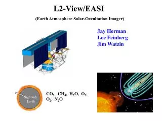
Earth Atmosphere Solar-Occultation Imager. Optics Cathy Marx [Dennis Evans] 2 August 2002. General System Description. Main Pupil Radius = 4400 mm Individual Telescopes Afocal, dual paraboloid Primary Aperture = 425 mm radius (needs to be 400 mm) Vertex Radius = -2631.578947 mm

E N D
Earth AtmosphereSolar-Occultation Imager Optics Cathy Marx [Dennis Evans] 2 August 2002
General System Description • Main Pupil • Radius = 4400 mm • Individual Telescopes • Afocal, dual paraboloid • Primary • Aperture = 425 mm radius (needs to be 400 mm) • Vertex Radius = -2631.578947 mm • Secondary • Aperture = 24 mm radius (to 30 to shadow Fold 1) • Vertex Radius = -131.578947 mm • Intervertex Distance • 1250 mm
General System Description • Afocal Telescope Center Locations • -4000, -2000, 0, 3000, 4000 mm • Even integral spacing is causing extra flux in PSF ‘wings’. • Combiner Telescope • Ritchey-Chretien • Prescription: EASI NS - 2dce-a-no obsc-PLEN OK.ZMX • 250 mm off center. • Plate Scale from spot diagram • One arc second = 1.833 mm • Effective Focal Length = 378151.4572 mm • Airy Radius (2µ) 425 mm radius aperture = 1.085 mm • 4400 mm radius aperture = 0.105 mm
Status • Delay Lines • Being located so they don’t exceed boom length • Being located on opposite sides of centerline to avoid interference • This may increase the size of the combiner significantly • Collector Spacing • Even dimension spacing causes excess flux in “wings” of PSF interferogram • ZEMAX Tech Support • PLEN (Path Length) misses surface problem in Merit Function Editor
X-fan Layout; Telescope 1 at X= -0 mmCombiner is at X= 1000 mm
Five Telescope Image InterferogramAlternate Spacing; Combiner at 0