Download
1 / 1
10 likes | 130 Vues
Bio-Engine Longevity Test (CCNY-Chapter): Seeking a Third World Energy and Development Solution Yesid Agualimpia , Julian Laverde , Kevin Beteta and Paul A.West (Faculty Mentor) Grove School of Engineering, City College of New York, New York, USA. Pre-heating System (VOW2)

E N D
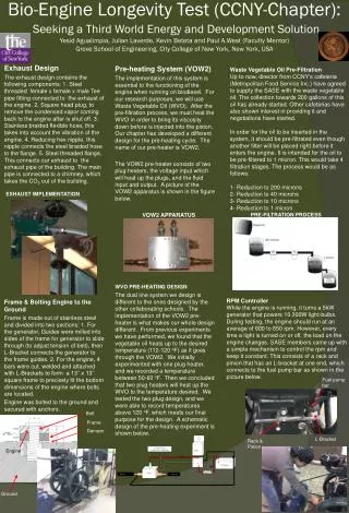
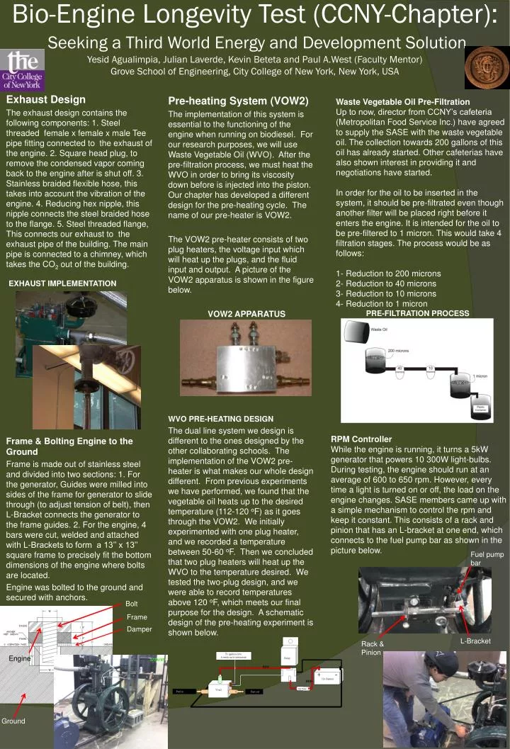
Bio-Engine Longevity Test (CCNY-Chapter):Seeking a Third World Energy and Development SolutionYesidAgualimpia, Julian Laverde, Kevin Beteta and Paul A.West (Faculty Mentor)Grove School of Engineering, City College of New York, New York, USA Pre-heating System (VOW2) The implementation of this system is essential to the functioning of the engine when running on biodiesel. For our research purposes, we will use Waste Vegetable Oil (WVO). After the pre-filtration process, we must heat the WVO in order to bring its viscosity down before is injected into the piston. Our chapter has developed a different design for the pre-heating cycle. The name of our pre-heater is VOW2. The VOW2 pre-heater consists of two plug heaters, the voltage input which will heat up the plugs, and the fluid input and output. A picture of the VOW2 apparatus is shown in the figure below. VOW2 APPARATUS WVO PRE-HEATING DESIGN The dual line system we design is different to the ones designed by the other collaborating schools. The implementation of the VOW2 pre-heater is what makes our whole design different. From previous experiments we have performed, we found that the vegetable oil heats up to the desired temperature (112-120 oF) as it goes through the VOW2. We initially experimented with one plug heater, and we recorded a temperature between 50-60 oF. Then we concluded that two plug heaters will heat up the WVO to the temperature desired. We tested the two-plug design, and we were able to record temperatures above 120 oF, which meets our final purpose for the design. A schematic design of the pre-heating experiment is shown below. Waste Vegetable Oil Pre-Filtration Up to now, director from CCNY’s cafeteria (Metropolitan Food Service Inc.) have agreed to supply the SASE with the waste vegetable oil. The collection towards 200 gallons of this oil has already started. Other cafeterias have also shown interest in providing it and negotiations have started. In order for the oil to be inserted in the system, it should be pre-filtrated even though another filter will be placed right before it enters the engine. It is intended for the oil to be pre-filtered to 1 micron. This would take 4 filtration stages. The process would be as follows: 1- Reduction to 200 microns 2- Reduction to 40 microns 3- Reduction to 10 microns 4- Reduction to 1 micron Exhaust Design The exhaust design contains the following components: 1. Steel threaded female x female x male Tee pipe fitting connected to the exhaust of the engine. 2. Square head plug, to remove the condensed vapor coming back to the engine after is shut off. 3. Stainless braided flexible hose, this takes into account the vibration of the engine. 4. Reducing hex nipple, this nipple connects the steel braided hose to the flange. 5. Steel threaded flange, This connects our exhaust to the exhaust pipe of the building. The main pipe is connected to a chimney, which takes the CO2 out of the building. EXHAUST IMPLEMENTATION Frame & Bolting Engine to the Ground Frame is made out of stainless steel and divided into two sections: 1. For the generator, Guides were milled into sides of the frame for generator to slide through (to adjust tension of belt), then L-Bracket connects the generator to the frame guides. 2. For the engine, 4 bars were cut, welded and attached with L-Brackets to form a 13’’ x 13’’ square frame to precisely fit the bottom dimensions of the engine where bolts are located. Engine was bolted to the ground and secured with anchors. PRE-FILTRATION PROCESS RPM Controller While the engine is running, it turns a 5kW generator that powers 10 300W light-bulbs. During testing, the engine should run at an average of 600 to 650 rpm. However, every time a light is turned on or off, the load on the engine changes. SASE members came up with a simple mechanism to control the rpm and keep it constant. This consists of a rack and pinion that has an L-bracket at one end, which connects to the fuel pump bar as shown in the picture below. Fuel pump bar Bolt Frame Damper L-Bracket Rack & Pinion Engine Ground