Download
1 / 131
1.45k likes | 1.9k Vues
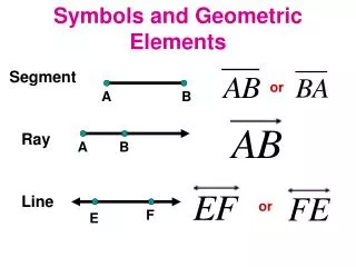
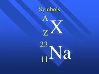
Geometric Symbols. ME 142 ENGINEERING DRAWING & GRAPHICS (Dimensioning). Introduction. Dimensioning components. Dimensioning object’ s features. Placement of dimensions. LECTURE OBJECTIVES. Example : Line conventions in engineering drawing. Meaning of Lines.

E N D
ME 142 ENGINEERING DRAWING & GRAPHICS (Dimensioning)
Introduction Dimensioning components Dimensioning object’ s features Placement of dimensions. LECTURE OBJECTIVES
Meaning of Lines Visible lines represent features that can be seen in the current view Hidden lines represent features that can not be seen in the current view Center linerepresents symmetry, path of motion, centers of circles, axis of axisymmetrical parts Dimension and Extension linesindicate the sizes and location of features on a drawing
Continuous thick line Visible line Dimension line Extension line Leader line Continuous thin line Dash thick line Hidden line Chain thin line Center line Basic Line Types Name according to application Types of Lines Appearance
Sketches of ideas Multiview Drawing Shape ENGINEERING DESIGN PROCESS RESULT TRANSFERRED INFORMATION Design a part Create drawings 1. Size, Location Dimensioning 2. Non-graphic information Manufacture
DEFINITION Dimensioning is the process of specifying part’ s information by using of figures,symbolsand notes. This information are such as: 1. Sizes and locations of features 2. Material’s type 3. Number required 4. Kind of surface finish 5. Manufacturing process 6. Size and geometric tolerances
DIMENSIONING SYSTEM 1. Metric system : ISO and JIS standards Examples 32, 32.5, 32.55, 0.5 (not .5) etc. 2. Decimal-inch system Examples 0.25 (not .25), 5.375 etc. 3. Fractional-inch system , Examples etc.
Extension lines Dimension lines(with arrowheads) Leader lines Dimension figures Notes :- local note - general note DIMENSIONING COMPONENTS Drawn with 4Hpencil Lettered with 2Hpencil.
EXTENSION LINES indicate the location on the object’s features that are dimensioned.
DIMENSION LINES indicate the direction and extent of a dimension, and inscribe dimension figures. 10 27 13 123o 43
LEADER LINES indicate details of the feature with a localnote. 10 27 10 Drill, 2 Holes R16 13 123o 43
Leave a visible gap(≈ 1 mm) from a view and start drawing an extension line. Extend the lines beyond the (last) dimension line 1-2 mm. EXTENSION LINES COMMON MISTAKE Visible gap
Do not break the lines as they cross object lines. EXTENSION LINES COMMON MISTAKE Continuous
Dimension lines should not be spaced too closeto each other and to the view. DIMENSION LINES Leave a space at least 2 times of a letter height. 16 11 34 35 Leave a space at least 1 time of a letter height.
The height of figures is suggested to be 2.5~3 mm. Place the numbers at about 1 mm above dimensionline and between extension lines. 34 11 DIMENSION FIGURES COMMON MISTAKE 11 34
When there is not enough space for figure or arrows, put it outside either of the extension lines. DIMENSION FIGURES Not enough space for figures Not enough space for arrows 16.25 1 1 1 16.25 or
Length dimension in millimeters without specifying a unit symbol “mm”. Angular dimension in degree with a symbol “o” place behind the figures (and if necessary minutes and seconds may be used together). DIMENSION FIGURES : UNITS The JIS and ISO standards adopt the unit of
DIMENSION FIGURES : ORIENTATION 1. Aligned method The dimension figures are placed so that they are readable from the bottom and right sideof the drawing. 2. Unidirectional method The dimension figures are placed so that they can be read from the bottom of the drawing. Do not use both system on the same drawing or on the same series of drawing (JIS Z8317)
30 30 30 30 30 30 30 30 EXAMPLE : Dimension of length using aligned method.
30 30 30 30 30 30 30 30 EXAMPLE : Dimension of length using unidirectional method.
EXAMPLE : Dimension of angle using aligned method. 45o 45o 45o 45o 45o 45o 45o 45o
45o 45o 45o 45o 45o 45o 45o 45o EXAMPLE : Dimension of angle using unidirectional method.
Place the notes near to the feature which they apply, and should be placed outside the view. Always read horizontally. 10 Drill ≈ 10mm 10 Drill LOCAL NOTES COMMON MISTAKE 10 Drill Too far
Clear Complete • Facilitate the • - manufacturing method • measurement method THE BASIC CONCEPT Dimensioning is accomplished by adding size and location information necessary to manufacture the object. This information have to be
L L L L S S S S EXAMPLE Designed part To manufacture this part we need to know… 1. Width, depth and thickness of the part. 2. Diameter and depth of the hole. “S” denotes size dimension. “L” denotes location dimension. 3. Location of the holes.
To dimension an angle use circular dimension line having the center at the vertex of the angle. ANGLE COMMON MISTAKE
ARC Arcs are dimensioned by giving the radius, in the views in which their true shapes appear. The letter “R” is always lettered before the figures to emphasize that this dimension is radius of an arc. R 200 R 200 or
ARC The dimension figure and the arrowhead should be inside the arc, where there is sufficient space. Sufficient space for both. Sufficient space for arrowhead only. Insufficient space for both. Move figure outside Move both figure and arrow outside R 62.5 R 200 R 6.5 R 58.5
ARC Leader line must be radial and inclined with an angle between 30 ~ 60 degs to the horizontal. R62.5 R62.5 R62.5 R62.5 R62.5 COMMON MISTAKE 60o R62.5 30o
ARC Use the foreshortened radial dimension line, when arc’ s center locates outside the sheet or interfere with other views. Drawing sheet Method 1 Method 2
FILLETS AND ROUNDS If all fillets and rounds are uniform in size, dimension may be omitted, but it is necessary to add the note “ All fillets and round are Rxx. ” Give the radius of a typical fillet only by using a local note. R6.5 R12 Drawing sheet NOTE: All fillets and round are R6.5 NOTE: All fillets and round are R6.5 unless otherwise specified.
CURVE The curve constructed from two or more arcs, requires the dimensions of radii and center’s location. Tangent point COMMON MISTAKE
CYLINDER Size dimensions are diameter and length. Location dimension must be located from its center lines and should be given in circular view. Measurement method
CYLINDER Diameter should be given in a longitudinal view with the symbol “ ” placed before the figures. 100 70
HOLES Size dimensions are diameter and depth. Location dimension must be located from its center lines and should be given in circular view. Measurement method
HOLES : SMALL SIZE Use leader line and local note to specify diameter and hole’s depth in the circular view. fxx Thru. fxx xx Drill. xx Drill, Thru. 1) Through thickness hole or or or
HOLES : SMALL SIZE Use leader line and local note to specify diameterand hole’s depth in the circular view. fxx, yy Deep xx Drill, yy Deep Hole’s depth 2) Blind hole or