Download
1 / 88
880 likes | 967 Vues
Polarized Source Development Run Results. Riad Suleiman Injector Group November 18, 2008. Outline. Injector Parity DAQ and Helicity Board Pockels Cell Alignment Fast Helicity Reversal Studies: 30 Hz, 250 Hz and 1 kHz BPMs Electronics Search for 60 Hz Noise Halls A & C Beams Crosstalk

E N D
Polarized Source Development Run Results Riad Suleiman Injector Group November 18, 2008
Outline • Injector Parity DAQ and Helicity Board • Pockels Cell Alignment • Fast Helicity Reversal Studies: • 30 Hz, 250 Hz and 1 kHz • BPMs Electronics • Search for 60 Hz Noise • Halls A & C Beams Crosstalk • Summary and Future Parity Beam Studies Thanks to: Roger Flood, Pete Francis, Paul King, Bob Michaels, Julie Roche
Notes: For each BPM, the wires are: +X+, +X-, +Y+, +Y-. BPM 0R06 is not connected yet. There are only two injector BPMs we are not reading: 0R03 and 0R04.
Helicity Board Outputs (Fiber-optic Signals): Real time helicity → Helicity Magnets, Pockels Cell and IA’s QRT → Halls and Mott Polarimeters MPS (T_Settle) → Halls and Mott Polarimeters Reporting Helicity → Halls, Mott Polarimeters, iocse9 and iocse14 Pair Sync → Halls and Mott Polarimeters
Helicity Board Software • We only have two choices of helicity reversal rates at any given time: • 30 Hz and 250 Hz or 30 Hz and 1 kHz. • To change the helicity reversal rate, a new code must be uploaded in the field to the helicity ioc • For both helicity reversal rates, a common choice of T-Settle (4 options): • 500, 200, 100, and 60 µs or 500, 100, 60, and 10 µs • Reporting Delay: No Delay, 2, 4, or 8 Cycles • Helicity Pattern: Pair (+- or -+) or Quartet (-++- or +--+) • Helicity Generation: Toggle or Pseudorandom (24-Bit Shift Register that repeats every 13 days at 30 Hz) • Free running: for example at 30 Hz, • f = 29.xx Hz = 1/(T_Settle+ Integration Window) • We are re-designing the Helicity Board
Notes: These values as measured by a scope Signals to Parity DAQ: MPS (T_Settle), QRT, Reporting Helicity, and Pair-Sync The length and frequency of Pair-Sync are identical to Helicity The length of QRT is identical to Helicity The integration window is generated by MPS AND Pair-Sync The integration window for 30 Hz is 33.33 ms and for 250 Hz it is 3.92 ms
Notes: These values as measured by a scope The integration window for 1 kHz is 0.980 ms
Parity ADC Internal Programming (for this study) • For 30 Hz helicity reversal: • Acquisition starts 40 µs after the gate begins • There are 4 blocks of 4161 samples/block for each gate. • The acquisition time is 33.328 ms • For 250 Hz helicity reversal: • Acquisition starts 40 µs after the gate begins • There are 4 blocks of 485 samples/block for each gate. • The acquisition time is 3.880 ms • For 1 kHz helicity reversal: • Acquisition starts 40 µs after the gate begins • There are 4 blocks of 117 samples/block for each gate. • The acquisition time is 936 µs
Battery Signals (3 V)Random, 8-Cycles Delay, Run 361 Bad ADC Channels
Battery SignalsBattery1 and Battery2 Round Trip to Laser Table Random, 8-Cycles Delay, Run 398 Random, No Delay, Run 406
Pockels Cell OFF Random, 8-Cycles Delay, Run 499 Random, No Delay, Run 502 No Helicity pickup
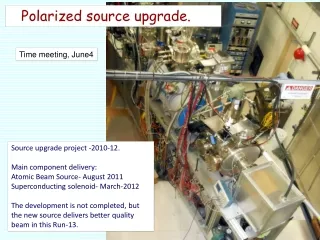
Pockels Cell Alignment • The Pockels Cell rise time was measured with a laser beam to be about 80 µs • With a Spinning Half Wave Plate or a Spinning Linear Polarizer and a Scope, the Circular polarization was maximized by checking: • Laser isogyro pattern • Pockels Cell Pitch, Yaw, Roll, X & Y • Pockels Cell Voltages • The above was checked for IHWP IN and OUT and for 30 Hz and 250 Hz helicity reversal • The Circular polarization = 99.97 %, and the Linear Polarization = 2.56 %
T-Settle Study (500, 200, 100, 60 µs) • 30 Hz • Run 399: PC OFF, IHWP IN, 500 µs • Run 381: IHWP OUT, 500 µs • Run 382: IHWP IN, 500 µs • Run 383: IHWP IN, 200 µs • Run 384: IHWP IN, 100 µs • Run 385: IHWP IN, 60 µs
BCM0L02 is broken IA is not OFF
Total ? Block 1 Block 2 Block 3 Block 4
T-Settle Study (500, 200, 100, 60 µs) • 250 Hz • Run 391: PC OFF, IHWP IN, 500 µs • Run 394: IHWP OUT, 500 µs • Run 392: IHWP IN, 500 µs • Run 395: IHWP IN, 200 µs • Run 396: IHWP IN, 100 µs • Run 397: IHWP IN, 60 µs