Download
1 / 7
70 likes | 139 Vues
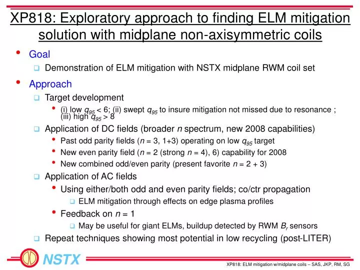
XP818: Exploratory approach to finding ELM mitigation solution with midplane non-axisymmetric coils. Goal Demonstration of ELM mitigation with NSTX midplane RWM coil set Approach Target development

E N D
XP818: Exploratory approach to finding ELM mitigation solution with midplane non-axisymmetric coils • Goal • Demonstration of ELM mitigation with NSTX midplane RWM coil set • Approach • Target development • (i) low q95 < 6; (ii) swept q95 to insure mitigation not missed due to resonance ; (iii) high q95 > 8 • Application of DC fields (broader n spectrum, new 2008 capabilities) • Past odd parity fields (n = 3, 1+3) operating on low q95 target • New even parity field (n = 2 (strong n = 4), 6) capability for 2008 • New combined odd/even parity (present favorite n = 2 + 3) • Application of AC fields • Using either/both odd and even parity fields; co/ctr propagation • ELM mitigation through effects on edge plasma profiles • Feedback on n = 1 • May be useful for giant ELMs, buildup detected by RWM Br sensors • Repeat techniques showing most potential in low recycling (post-LITER)
XP818 ELM Mitigation run on two days last week Task Number of Shots 1) Create target plasmas A) Create q95 < 6 target: (generate at least 10 ELMs with approximately even spacing) (q95 ~ 5.5 is adequate) - Use shot 124349 as setup shot, (Ip = 0.8 MA, Bt = 0.5 T), change NBI source C to 1 MW unmodulated 2 - Raise Ip to 0.9 MA; change Bt to 0.45T, then 0.40T 3 - If q95 > 6 and insufficient ELMs, perform startup optimizations as per J. Menard to raise qmin. (8) B) Create q95 ramp target - Start from low q95 target created in step (1A), Ip flat-top to 0.7 MA, ramping up to 1.0 MA; adjust eventual Ip flat-top if needed to create steady ELMs. 4 - if plasma drops out of H-mode, start Ip ramp from 1.0 MA ramping to 0.7 MA (2) - vary Bt to change range of q ramp (optional) (2) C) Create q95 > 8 target - Use shot 124349 as setup shot, (Ip = 0.8 MA, Bt = 0.5 T), change NBI source C to 1 MW unmodulated - Drop Ip to 0.7 MA; tweak to 0.75 MA if desired 2 2) Attempt ELM mitigation with non-axisymmetric fields under normal recycling conditions - DC fields: A) Apply n = 3 field configuration; vary amplitude from 1.5 kA 4 B) Apply n = 3 + 1 field configuration; vary amplitude from 1.0 kA, 0.5 kA 4 C) Apply n = 2 + 3 field configuration (start from RWM (1-4) 0.5kA, RWM (2,6) 0.5kA, RWM (3,5) 1.5 kA) 4 D) Apply n = 2 field configuration; vary amplitude from 1.5 kA 4 E) Apply n = 6 field configuration (primary field is n = 0); vary amplitude from 2.5 kA 3 - AC fields (pre-programmed): F) Apply n = 3; vary f above/below ELM frequency; vary amplitude from 2.0 kA 4 G) Apply n = 1 (co-propagating); vary f above/below ELM frequency; vary amplitude 4 H) Apply n = 1 (ctr-propagating); vary f above/below ELM frequency; vary amplitude 4 - AC fields (n = 1 feedback): I) n = 1 Br feedback: giant ELM target (e.g. 125271), vary (i) gain (ii) phase 6 3) Attempt ELM mitigation with non-axisymmetric fields under reduced recycling conditions 16 Total (optional): 64 (12) Shots taken (3/3/08 + 3/7/08) Shots being considered for 3/24 run V1.4
Considerations for next run – for discussion • Target development • Low q95 target • We’ve worked on this quite a bit - what are the goals? • Effects on ELMs so far not restricted to a narrow q95 range (good thing!) • Should still have q95 swept through shot, or changed between shots • Applied fields • Discussion so far aims toward completing plan of n = 2 + 3 field • What exact patch panel to use? • Run DC and AC variants? • Propagate field toroidally? • Had an effect in past experiment • Suggest to run amplitude scan for most favorable condition • Note: Effect on ELMs so far not highly sensitive to applied field • Dependence on field configuration (n = odd, even) and application (AC, DC) not yet concluded
XP818 ELM Mitigation - Run plan 3/24/08 Task Number of Shots 0) SPA polarity check shot (check RWM coil connections) 1 1) Reproduce PHAT ELMs using n = 2 field configuration (compare to 127531); vary n = 2 amplitude (optional) 2 2) Create lowered q95 < 6 target (control shots – no non-axisymmetric field) (use 127541 as setup shot; Bt = 0.39T, Ip = 0.8 MA)) A) Raise Ip = 0.9 MA, 2 NBI sources 1 B) Retake shot (2A) above with 1 NBI source 1 C) If (2B) fails H-mode, retake with 2nd NBI stepped down later in shot 2 3) Evaluate new plasma target with non-axisymmetric fields A) n = 2 DC field with new target plasma created from step (2) 2 B) n = 2 AC field if null result in step (3A) 1 C) Choose what target shot to use based on shots above, and continue 4) Attempt ELM mitigation with non-axisymmetric fields (field amplitude scans) A) n = 2 + 3 DC field configuration, vary field amplitude 4 B) n = 2 + 3 AC standing field configuration, vary field amplitude 3 C) n = 3 DC field configuration, vary field amplitude 4 D) n = 3 AC standing field configuration, vary field amplitude 3 E) Vary timing of non-axisymmetric field pulse to demonstrate correlation of field and ELM change 2 5) Additional scans (if time allows) A) Apply most successful non-axisymmetric field to higher q95 target plasma (2) B) Apply best AC field configuration with toroidal phase shifts on each SPA current (2) C) Take SPA shots (one fore each unit) for sensor calibration (3) Total 26 (33) V1.1
XP818 successful so far in changing ELM frequency • ELM frequency initially reduced with application of AC fields • First shown with n = 3 AC standing wave, then n = 2 AC • AC fields allow application of greater peak RWM coil current before plasma rotation damping becomes too severe • Also shown with DC fields • Jokingly named: “Pulsed High Amplitude Transient” – PHAT ELMs • Longer duration (multi-filament), lower frequency than Type I • Key to now understand the effect - aim for mitigation • Effect is not restricted to a narrow range of q95 – a good thing! • Mitigation in DIII-D shown to be sensitive to q95 • Effect is apparently not highly sensitive to applied field • Clear dependence on field amplitude • Dependence on field configuration (n = odd, even) and application (AC, DC) not yet concluded • Frequency ~ 50Hz largely independent of applied field • Variation of plasma quantity is affecting ELM
Reduced ELM frequency observed in several applied field configurations • Timing of PHAT ELMs correlated to timing of applied field in dedicated shots n = 3 AC field, 70 Hz, 3.8 kA peak-to-peak n = 2 AC field, 70 Hz, 5.5 kA peak-to-peak Ip (kA) IRWM (A) Da(arb) t (s) t (s)