Download
1 / 50
500 likes | 619 Vues
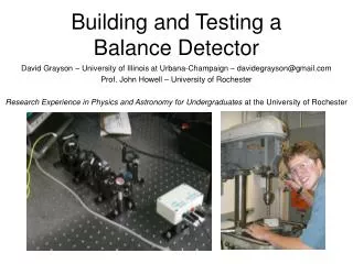
Veljko Grilj Ruđer Bošković Institute, Zagreb, Croatia. Detector testing facility a t RBI (IBIC ( Ion Beam Induced Charge ) experiment). Silicon Detector Workshop Split, Croatia, 8-10 October 2012. 1. Accelerators. 1.0 MV HVE Tandetron accelerator.

E N D
VeljkoGrilj RuđerBošković Institute, Zagreb, Croatia Detector testing facility at RBI(IBIC (Ion Beam Induced Charge) experiment) Silicon Detector Workshop Split, Croatia, 8-10 October 2012
1. Accelerators 1.0 MV HVE Tandetron accelerator 6.0 MV EN Tandem Van de Graaff accelerator PIXE/RBS 1 Ion microprobe In-air PIXE 2 Det. test. IBIC PIXE crystal spectrometer Nuclear reactions Dual-beam irradiation IAEA beam line TOF ERDA
1.1. New detector testing beam line 1. Beam deflector and/or scanner 2. Pre-chamber with beam degrader/diffuser 3. Final chamber with beam in air capability
1.2. Nuclear microprobe ION POSITION - focusing and scanning IONS - p, , Li, C, O,.. ION RATE - currents 0 -106 p/s RANGE - 2 to 200 m
1.3. Available ion beams • Accel. voltages 0.1 to 6.0 MV • Negative Ion sources: • Duoplasmatron • RF He • Sputtering I Cu Si C protons Eions = 1 MeV/amu MIPs
Vout Q V V 2. ION BEAM INDUCED CHARGE - theory Principles of radiation detection techniques Deposited energy Free charge genetration and transport Ouput signal Vout Vout = F (deposited energy, free carrier transport) Nuclear spectroscopy Well known
Vout Q V V 2. ION BEAM INDUCED CHARGE - theory Principles of IBIC Deposited energy Free charge genetration and transport Ouput signal Vout Vout = F (deposited energy, free carrier transport) Well known Material characterization
2. ION BEAM INDUCED CHARGE - theory Principles of IBIC b) Creation of e-h pairs a) Energy deposition by ions Bethe formula:
Vout T=0 Q d V V 2. ION BEAM INDUCED CHARGE - theory Principles of IBIC c) Free charge carrier transport → charge induced at electodes year 1964 Gunn’s theorem: v
Vout Q d V V 2. ION BEAM INDUCED CHARGE - theory Principles of IBIC c) Free charge carrier transport → charge induced at electodes Gunn’s theorem: T=1
Vout Q d V V 2. ION BEAM INDUCED CHARGE - theory Principles of IBIC c) Free charge carrier transport → charge induced at electodes Gunn’s theorem: T=2
Vout Q d V V 2. ION BEAM INDUCED CHARGE - theory Principles of IBIC c) Free charge carrier transport → charge induced at electodes Gunn’s theorem: T=3
Vout Q d V V 2. ION BEAM INDUCED CHARGE - theory Principles of IBIC c) Free charge carrier transport → charge induced at electodes Gunn’s theorem: T=4
Vout Q d V V 2. ION BEAM INDUCED CHARGE - theory Principles of IBIC c) Free charge carrier transport → charge induced at electodes Gunn’s theorem: T=5
Vout Q d V V 2. ION BEAM INDUCED CHARGE - theory Principles of IBIC c) Free charge carrier transport → charge induced at electodes Gunn’s theorem: T=6
Vout Q d V V 2. ION BEAM INDUCED CHARGE - theory Principles of IBIC c) Free charge carrier transport → charge induced at electodes Gunn’s theorem: T=7
Vout Q d V V 2. ION BEAM INDUCED CHARGE - theory Principles of IBIC c) Free charge carrier transport → charge induced at electodes Gunn’s theorem: T=8
Vout Q d V V 2. ION BEAM INDUCED CHARGE - theory Principles of IBIC c) Free charge carrier transport → charge induced at electodes Gunn’s theorem: T=9
Vout Q d V V 2. ION BEAM INDUCED CHARGE - theory Principles of IBIC c) Free charge carrier transport → charge induced at electodes Gunn’s theorem: T=10
Vout Q d V V 2. ION BEAM INDUCED CHARGE - theory Principles of IBIC c) Free charge carrier transport → charge induced at electodes Gunn’s theorem: T=11
2. ION BEAM INDUCED CHARGE - theory Principles of IBIC Impact of defects on charge carriers mobility: - physical opservable:
2. ION BEAM INDUCED CHARGE - theory Principles of IBIC - direct implication from Gunn’s theorem: - consequences: a) ion beam -V0 CCE 100% holes electrons b) - V0 - V0 he
2. ION BEAM INDUCED CHARGE - theory Principles of IBIC • Advantages of using focused ions: • spatial resolution • wide spread of ion ranges 4 MeV H+ in Si 47 mm Electrons 10 keV 90 mm 20 mm 147 mm 2 mm 4 mm 2 MeV H+ in Si 3 MeV H+ in Si Electrons 40 keV 6 mm 20 mm
2. ION BEAM induced charge Samples PIN diode
2. ION BEAM induced charge Samples Si DSSD (16x16 strips) Ion beam CdInGaSe solar cell Laura Grassi, Wednesday, 16:00h CVD diamond
2. ION BEAM induced charge Geometries 100 m
Si Schotky diode 3. IbiceXAMPLES Frontal IBIC 4.5 MeV Li range 6μm surface 3 MeV protons range 90 μm - by proper selection of ion type and energy, CCE (charge collection efficiency) at different sample depths can be imaged. bulk
Si Schotky diode 3. IbiceXAMPLES Frontal IBIC – depth profiling 4.5 MeV Li7 ions (range in Si 8.5 m) 7.875 O16 ions (range in Si 4.5 m) Li image - O image / 2.8 IBIC between 4.5 and 8.5 m
4H-SiC diode 3. IBIC EXamples Frontal IBIC – drift & diffusion drift diffusion minority carrier diffusion length E ≠ 0 E = 0
4H-SiC diode 3. IBIC EXamples Frontal IBIC – drift & diffusion drift diffusion E ≠ 0 E = 0
4H-SiC diode 3. IBIC EXamples Frontal IBIC – drift & diffusion drift diffusion E ≠ 0 E = 0
4H-SiC diode 3. IBIC EXamples Frontal IBIC – drift & diffusion drift diffusion - direct measurement of diffusion length E ≠ 0 Lp = (9.0±0.3) μm
CdZnTe 3. IBIC EXamples • sample thickness > 2 mm • IBIC with 2 MeV p+, range < 30 μm Frontal IBIC – μτ mapping • from Gunn’s theorem with assumptions of full depletion, • constant electric field and generation near one electrode: Hecht equation holes electrons M. Veale et al., IEEE TNS, 2008
Si power diode 3. IBIC EXamples Lateral IBIC – drift and diffusion ion beam pn junction E < 0 E = 0 z zd 0 CCE (z<zd)≈ 1 CCE (z>zd)= exp(-(z-zd)/Lp,n) hole or electron diffusion length
CdZnTe 3. IBIC EXamples Temperature dependent lateral IBIC 3 MeV proton beam - temperature range 166-329 K Bias Preamplifier Amplifier IBIC MAPS X-Y scanning ADC DAQ Au-contacts CdZnTe DSO Digital oscilloscope Cooling-heating TRIBIC
CdZnTe 3. IBIC EXamples Temperature dependent lateral IBIC IBIC line scan (anode to cathode) for CCE=100% (mt)e=(1.4)*10-3 cm2/V (mt)h=1*10-5 cm2/V
3. IBIC EXamples Radiation hardness tests Ion beam induced damage: IBIC on-line monitoring: 6 Li7m-2 = 6×108cm-2 (4 events per pixel) 50 Li7m-2 = 5×109cm-2 - For 100% ion impact detection efficiency, IBIC can be used to monitor irradiation fluence - Irradiation of arbitrary shapes - On-line monitoring of CCE degradation
Si diode 3. IBIC EXamples Radiation hardness tests Irradiation pattern (3 x3 quadrants, 50 x 50 pixels, 100 x 100 m2 each, 20 m gaps, tirrad = 5 min. – 3 h ) - damage done with He, Li, O & Cl ions of similar range
Si diode 3. IBIC EXamples Radiation hardness tests • Modeling of CCE: • doping profiles & el. field (CV) • drift velocity profiles (el. field) • hole contribution negligible • vacancy profile (SRIM) • predominantly divacancies (DLTS) • dE/dx from (SRIM) • - electron lifetime: effective fluence k = 0.88 *10-15 k = 0.18 !! 18% of radiation induced defects leads to stable divacancies !
4. ion INDUCED dlts Radiation produces lattice defects el. active traps, CCE<100% Question: how to calculate the energy levels of produced traps? Answer: DLTS, but what if.....a) number of traps is very very large? b) I want good spatial resolution? c) my sample is diamod?
4. ion INDUCED dlts Radiation produces lattice defects el. active traps, CCE<100% Question: how to calculate the energy levels of produced traps? Answer: DLTS, but what if.....a) number of traps is very very large? b) I want good spatial resolution? c) my sample is diamod? Ion Induced DLTS Steps: • IBIC with MeV ions, charge carriers will fill traps • record cumulative collected charge in time using charge sensitive preamp • and digital scope at different temperatures • choose rate windows like in conventional DLTS • plot Q(t2)-Q(t1) vs. T • make Arrhenius analysis and get activation energy of the defect
4. ion INDUCED dlts 6H-SiC diode N. Iwamoto et al., IEEE TNS, 2011 - irradiation with 1 MeV electrons, el. active traps, CCE<100% • IBIC with 5.486 MeV alphas cumulative collected charge 250K<T<320 K Q(t2)-Q(t1) vs. T IIDLTS DLTS Estimated activation energy: 0.50±0.05 eV 0.53±0.07 eV
400 μm thick natural diamond 5. Time resolved IBIC - tribic (transient current technique, TCT) • use of current sensitive amplifier instead of charge sensitive • high frequency oscilloscope, • novel technique ??? C. Canali, E. Gatti, S.F. Koslov, P.F. Manfredi, C. Manfredotti, F. Nava, A. QuiriniNucl. Instr. Meth. 160 (1979) 73-77
5. Time resolved IBIC - tribic TCT on scCVD diamond at low temperatures H. Jansen (CERN), CARAT Workshop, GSI, 2011 • 2 GHz, 40 dB, 200ps rise time amplifier (CIVIDEC) • broad-band 3GHz scope (LeCroy)
5. Time resolved IBIC - tribic Saturation velocity H. Jansen (CERN), CARAT Workshop, GSI, 2011 Lower fields are required to reach saturation velocity at low tempertures
5. Time resolved IBIC - tribic Plasma effects Plasma effects
5. Time resolved IBIC - tribic Charge trapping/detrapping H. Jansen (CERN), CARAT Workshop, GSI, 2011 Significantely higher charge trapping at low temperatures !!
5. Time resolved IBIC - tribic Charge trapping/detrapping H. Jansen (CERN), CARAT Workshop, GSI, 2011 Detrapping (~ 10 ns)
500 μm thick scCVD diamond 5. Time resolved ibic - tribic Position sensitivity • scCVD diamond, 500 μm thick • lateral scan with 4.5 MEV p • (μτ)e< (μτ)h • 6 GHz, 15dB preamp (Minicircuits) • 5 GHz, 10 GS/s scope (LeCroy) Achievable resolution ≈ 10 μm 0 500μm