Download
1 / 1
10 likes | 163 Vues
Grating line. q. F8. Polyimide. Substrate. TE 0. TE 1. n. ( b). ( a). ( d). ( c). Tunable lasers.

E N D
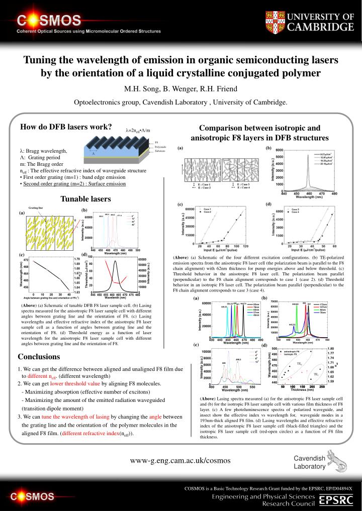
Grating line q F8 Polyimide Substrate TE0 TE1 n (b) (a) (d) (c) Tunable lasers (Above) (a) Schematic of tunable DFB F8 laser sample cell. (b) Lasing spectra measured for the anisotropic F8 laser sample cell with different angles between grating line and the orientation of F8. (c) Lasing wavelengths and effective refractive index of the anisotropic F8 laser sample cell as a function of angles between grating line and the orientation of F8. (d) Threshold energy as a function of laser wavelength for the anisotropic F8 laser sample cell with different angles between grating line and the orientation of F8. Tuning the wavelength of emission in organic semiconducting lasers by the orientation of a liquid crystalline conjugated polymer M.H. Song, B. Wenger, R.H. Friend Optoelectronics group, Cavendish Laboratory , University of Cambridge. How do DFB lasers work? Comparison between isotropic and anisotropic F8 layers in DFB structures l=2neff•Λ/m l: Bragg wavelength, Λ: Grating period m: The Bragg order neff : The effective refractive index of waveguide structure • First order grating (m=1) : band edge emission • Second order grating (m=2) : Surface emission (Above) (a) Schematic of the four different excitation configurations. (b) TE-polarized emission spectra from the anisotropic F8 laser cell (the polarization beam is parallel to the F8 chain alignment) with 62nm thickness for pump energies above and below threshold. (c) Threshold behavior in the anisotropic F8 laser cell. The polarization beam parallel (perpendicular) to the F8 chain alignment corresponds to case 1 (case 2). (d) Threshold behavior in an isotropic F8 laser cell. The polarization beam parallel (perpendicular) to the F8 chain alignment corresponds to case 3 (case 4). (b) (a) (c) (d) Conclusions • We can get the difference between aligned and unaligned F8 film due to different neff.(different wavelength) • 2.We can get lower threshold value by aligning F8 molecules.- Maximizing absorption (effective number of excitons)- Maximizing the amount of the emitted radiation waveguided (transition dipole moment) • 3. We can tune the wavelength of lasing by changing the angle between the grating line and the orientation of the polymer molecules in the aligned F8 film. (different refractive index(neff)). (Above) Lasing spectra measured (a) for the anisotropic F8 laser sample cell and (b) for the isotropic F8 laser sample cell with various film thickness of F8 layer. (c) A few photoluminescence spectra of -polarized waveguide, and insect show the effective index vs wavelength for, waveguide modes in a 193nm-thick aligned F8 film. (d) Lasing wavelengths and effective refractive index of the anisotropic F8 laser sample cell (black-filled triangles) and the isotropic F8 laser sample cell (red-open circles) as a function of F8 film thickness. CavendishLaboratory www-g.eng.cam.ac.uk/cosmos COSMOS is a Basic Technology Research Grant funded by the EPSRC, EP/D04894X