Download

1 / 21
210 likes | 242 Vues
Numerical calculation of dielectrophoretic forces acting on micro-scale particles. Dr Matt Praeger , Z Li, J M Smallwood and P L Lewin 15 th April 2015. Outline. PART 1: SPABRINK Project overview Calculations based on Pohl’s method PART 2: Maxwell Stress Tensor (MST) method

E N D
Numerical calculation of dielectrophoretic forces acting on micro-scale particles Dr Matt Praeger, Z Li, J M Smallwood and P L Lewin 15th April 2015
Outline PART 1: SPABRINK Project overview Calculations based on Pohl’s method PART 2: Maxwell Stress Tensor (MST) method Validation tests PART 3: Application of the MST method Application to experimental geometry PART 4: Further Work Conclusions
SPABRINK Project Internet connected billboard. Image made up of coloured powder. Switchable dielectrophoretic force holds the ink in place for display. Reusable powder based ink.
SPABRINK Project Dielectrophoretic force requires a divergent E-field. Interdigitated electrodes create this divergent E-field. Gap and track width 500µm. Operating voltage 1000V.
Calculations based on Pohl’s method DEP force Gradient of E-field2 Particle volume Clausius-Mossotti term
Previous Work Our application uses interdigitated electrodes to generate a diverging E-field 2D Electrostatic calculation of E-field Define the adhesion factor as the ratio of DEP force to particle mass. We can calculate the adhesion factor for any position in the E-field model. +ve adhesion (particles stick) Polymer sheet Air gap Foil substrate
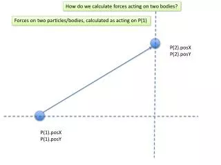
Maxwell Stress Tensor Method Surface normal Maxwell stress tensor Force on Particle Integral over particle surface Electric displacement field (ϵ0E) Normal of particle surface E-Field Transpose for tensor product Stress tensor in surrounding media
Maxwell Stress Tensor Method The arrow plots illustrate the direction and magnitude of the MST on the surface of a sphere: In a uniform E-field the contributions cancel each other out. In a diverging E-field there is a net force applied to the particle. Note – the previous Pohl calculations were based on 2D field models. For the MST method we are working in 3D. Uniform E-Field Divergent E-Field
Validation tests Q = charge on inner sphere
Validation tests • Close agreement between the analytical (Pohl) method and the numerical MST method in Comsol:
Comparison of Pohl & MST methods • The presence of the particle modifies the E-field in the MST method but not in Pohl’s method. • This is especially important in multi particle models or when the particle approaches a boundary. Pohl’s method MST method
Application of the MST method • The MST method allows us to model non-spherical particles. • Consider two cases for an ellipsoid particle inside a spherical capacitor: Aspect ratio Aspect ratio Rotation angle Rotation angle
Results 1: Red arrows represent Maxwell Stress • Fixed centre: Strongest force for prolate spheroid at θ =0° • Fixed nearest point: Smaller variation in DEP force. Strongest force for oblate spheroid at θ =90° Prolate R=3
Application of MST to experiment • Ellipsoid in proximity to interdigitated electrodes. • 3D model allows the ellipsoid to be in any orientation relative to the electrodes (only a 2d slice is shown below). • Aspect ratio and rotation angles θ and ϕ are all varied…
Results 2: Prolate Spheroid Oblate Spheroid • Strongest force when long axis traverses the electrode gap. • Could have a situation where an oblate spheroid falls off in certain orientations but the prolate spheroid always sticks.
Further Work Calculations with multiple particles. Allow particles to move under the influence of DEP forces. Predict the accumulation of particles at the edges of electrodes and in the insulating gaps. Forces in thick layers of particles?
Conclusions We have demonstrated 3D DEP force calculations using the Maxwell stress tensor method. (This is now relatively straightforward in Comsol). Agreement was verified between Pohl and MST type models. The DEP forces on non-spherical particles were calculated. DEP forces are effective for manipulating micro-scale particles. There is huge potential for use of DEP in industrial processes. The MST method could help us to engineer DEP based solutions to diverse challenges in particulate based industrial processes.
Thank You This project has received funding from the European Union’s Seventh Framework Programme for research, technological development and demonstration under grant agreement no 605299.