Download

1 / 44
440 likes | 609 Vues
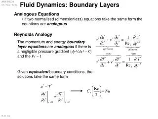
Convection in Flat Plate Turbulent Boundary Layers. P M V Subbarao Associate Professor Mechanical Engineering Department IIT Delhi. An Extra Effect For Same Dose ……. Transition to Turbulence.

E N D
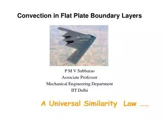
Convection in Flat Plate Turbulent Boundary Layers P M V Subbarao Associate Professor Mechanical Engineering Department IIT Delhi An Extra Effect For Same Dose ……
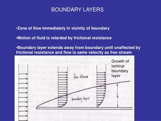
Transition to Turbulence • When the boundary layer changes from a laminar flow to a turbulent flow it is referred to as transition. • At a certain distance away from the leading edge, the flow begins to swirl and various layers of flow mix violently with each other. • This violent mixing of the various layers, it signals that a transition from the smooth laminar flow near the edge to the turbulent flow away from the edge has occurred.
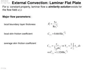
Turbulent Flow Regime • For a flat place boundary layer becomes turbulent at Rex ~ 5 X 10⁵. • The local friction coefficient is well correlated by an expression of the form Local Nusselt number:
Mixed Boundary Layer • In a flow past a long flat plate initially, the boundary layer will be laminar and then it will become turbulent. • The distance at which this transitions starts is called critical distance (Xc) measured from edge and corresponding Reynolds number is called as Critical Reynolds number. • If the length of the plate (L) is such that 0.95 Xc/L 1, the entire flow is approximated as laminar. • When the transition occurs sufficiently upstream of the trailing edge, Xc/L 0.95, the surface average coefficients will be influenced by both laminar and turbulent boundary layers.
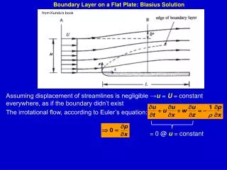
Flat Plate Boundary Layer Trasition • Important point: • Typically a turbulent boundary layer is preceded by a laminar boundary layer first upstream • need to consider case with mixed boundary layer conditions!
Leading Edge Trailing Edge Xc L
On integration: For a smooth flat plate: Rexc = 5 X 10⁵
For very large flat plates: L >> Xc, in general for ReL > 108
Convection for Cylinder in Cross Flow P M V Subbarao Associate Professor Mechanical Engineering Department IIT Delhi A Concept That Changed the Lifestyle of the World….
Industrial Applications • Many thermal industries used the equipment, where convection from cylinders in cross flow is present. • Super heaters, economizers in Power plant steam generators. • Condensers and feed water heaters in a power plant. • Radiators in automobiles. • Condenser and evaporator in a refrigerator or air conditioner. • Two most common equipment are: • Shell and tube heat exchanger. • Fin and tube heat exchanger.
Power Plant Steam Generator : Establish Heat Transfer from Hot Flue Gas to High Pressure Water
Basic Geometry of A Furnace 700 – 8000C 1000 – 12000C 1500 – 17000C 300 – 4000C
Furnace Exit Hot Exhaust gases Heat Radiation & Convection Flame Burner 1500 – 17000C
S1 S2 Convective Superheater (Pendant) • Convective super heaters are vertical type (Pendant ) or horizontal types. • The Pendant SH is always arranged in the horizontal crossover duct. • Pendant SH tubes are widely spaced due to high temperature and ash is soft. • Transverse pitch : S1/d > 4.5 • Longitudinal pitch : S2/d > 3.5. • The outside tube diameter : 32 – 51mm • Tube thickness : 3 – 7mm
S1 S2 Convective Superheater (Horizontal) • The horizontal SH are located in the back pass. • The tubes are arranged in the in-line configuration. • The outer diameter of the tube is 32 – 51 mm. • The tube thickness of the tube is 3 – 7 mm. • The transverse pitch : S1/d = 2 – 3. • The longitudinal pitch :S2/d = 1.6 – 2.5. • The tubes are arranged in multiple parallel sets. • The desired velocity depends on the type of SH and operating steam pressures. • The outside tube diameter : 32 – 51mm • Tube thickness : 3 – 7mm
Anatomy of Fin & Tube Heat Exchanger Liquid Flow Gas Flow Plate Tube
HVAC Fin and Tube Heat Exchangers • Fin and tube heat exchangers are used widely in residential, commercial and industrial HVAC applications. • HXs of different fin spacing are found in HVAC applications.
Generally the overall average Nusselt number for heat transfer with the entire object is important. As with a flat plate, correlations developed from experimental data to compute Nu as a f(Rem,Prn) Overall Average Nusselt number • All properties are evaluated at the freestream temperature, except Prs • which is evaluated at the surface temperature.
Values for C and m Expect an accuracy within 20% with these correlations
Cylinder in Cross Flow The empirical correlation due to Hilpert
D D Square Cylinder in Cross Flow Valid for 5 X 10³ < ReD < 105 Valid for 5 X 10³ < ReD < 105
D D Hexagonal Cylinder in Cross Flow Valid for 5 X 10³ < ReD <1.95X10⁴ Valid for 1.95X10⁴ < ReD < 105 Valid for 5 X 10³ < ReD < 105
Vertical Plate in Cross Flow Valid for 4 X 10³ < ReD < 1.5 X10⁴ D
Convection heat transfer with a sphere External flow and heat transfer relations are similar to those around a cylinder. Numerous correlations proposed from lab experiments, one being: All properties except ms are evaluated at T∞.
Convection heat transfer with banks of tubes • Typically, one fluid moves over the tubes, while a second fluid at a different temperature passes through the tubes. (cross flow) • The tube rows of a bank are staggered or aligned. The configuration is characterized by the tube diameter D, the transverse pitch ST and longitudinal pitch SL.
For Reynolds number or If staggered and
If number of tubes are less than 10, a correction factor is applied as: And values for C2 are from table
More recent results have been obtained by Zhukauskas. All properties except Prs are evaluated at the arithmetic mean of the fluid inlet and outlet temperatures. Values for C and m.
Array of Cylinders in Cross Flow : A Shell • The equivalent diameter is calculated as four times the net flow area as layout on the tube bank (for any pitch layout) divided by the wetted perimeter.
For square pitch: For triangular pitch:
Number of tube centre lines in a Shell: Dsis the inner diameter of the shell. Flow area associated with each tube bundle between baffles is: where A s is the bundle cross flow area, Ds is the inner diameter of the shell, C is the clearance between adjacent tubes, and B is the baffle spacing.
the tube clearance C is expressed as: Then the shell-side mass velocity is found with Shell side Reynolds Number: