Download
1 / 19
190 likes | 307 Vues
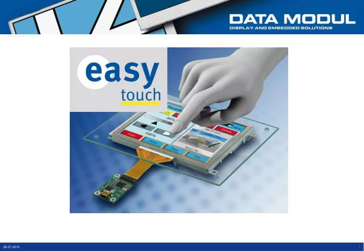
Key benefits. usage with protective glass up to 1cm thickness multi-touch function usage with gloves (latex, leather, rubber) maximising the range of utilisation high transmission ratio of 90% automatic calibration & drift compensation (freely definable)

E N D
Key benefits • usage with protective glass up to 1cm thickness • multi-touch function • usage with gloves (latex, leather, rubber) • maximising the range of utilisation • high transmission ratio of 90% • automatic calibration & drift compensation (freely definable) • extended temperature range (-20°C...+70°C) • excellent EMC and EMI behaviour • high flexibility integrating the touch controller • low power consumption (5V x 20mA) independent of the size of the touch panel 2
Function • The touch sensor consists of a multilayer ITO-foil(indium tin oxide) • Couples of electrodes generate an electrical field. • When a finger touches the panel the field coupling will change. The controller will detected the change and calculate the position.
Y5 Y4 Y3 Y2 Y1 Y0 X0 X1 X2 X3 X4 X5 X6 X7 Definition of the touch-area • X and Y-lines are defining the touch area (matrix-structure). • The numbers of measuring points is defined by the numbers of X- and Y-lines. E.g. 8 x 6 = 48 or 18 x12 = 216 (depending on the controller and the design of the foil). • By interpolation a theoretical resolution of 1024 x 1024 is possible (10bit). • The sensitivity of the touch could be adjusted by software.
Glas ITO-foil ITO-foil Dielectric Dielectric ITO-foil ITO-foil Structure of Touch-Sensor < 8.0” ≥ 8.0”
provided by: Data Modul customer Integration: Mouse-Driver (easyTouch controller) configuration-tool customer application USB operation system • Interface: only USB • Touch Function: • 1 Finger (Mouse Function), 2 finger usage (gestures) possible via API • 2 Finger usage (Win 7) • Data Modul provides Mouse-Driver, API and configuration-tool for all common operating systems (Windows, XP, 7, CE (5.0, 6.0), Vista, Linux,) • Easy calibration and linearization by software (Windows, XP, Vista, 7, CE, Linux) API X1,Y1 coordinates Touch-Panel easyTouch controlleror stamp and stamp master driver X1,Y1, X2,Y2 coordinates settings CPU
provided by: Data Modul customer Integration: I²C (Chip-Integration on custom-board)MOQ: 5k pcs configuration-tool customer application • No operating system necessary • Interface: I²C only • Touch-Function: real Multi-Touch-Function • Customer has to take care of the chip integration by himself. Data Modul will provide an application note. • Customer has to sign a NDA to get a protocolNDA_easyTouch:S:\Displaytechnik\Touch_Easy\Specifications\Controller\Atmel-Controller (single Chip) „operation system“ Atmel-Chip or „stamp“ I²C Touch-Panel driver X,Y coordinates settings Custom board CPU
Integration: Windows 7 with DigitizerMOQ: 5k pcs provided by: Data Modul customer customer application Operationsystem MS Touch-Kit Mouse USB (Windows 7) Touch-Panel easyTouch controller or„stamp + stamp master“ • Touch-Function: 2 Finger Mouse Function, , Multi-Touch via MS-Touch-Kit • Windows 7 only • Data Modul provides a configuration-tool to adjust the settings during the development phase • For the MP, the touch controller could be preinstalled (e.g. sensibility) according to the requirements of the customer. Multi-Touch Digitizer-Daten CPU
Sizes 10
Options of easyMaxTouch-Controller Touch-Chip USB-Chip USB Connector Touch-Panel Connector 1 USB easy(Max)Touch Controller Touch-Chip I²C USB-Chip USB Connector Touch-Panel 2 Connector USB Stamp Stamp Master I²C Touch-Chip USB-Chip Touch-Panel Connector 3 USB Stamp Stamp Master
Options of easyMaxTouch-Controller Touch-Chip Touch-Panel 4 Connector I²C Stamp I²C Touch-Chip Mikro-processor Touch-Panel Connector 5 SPI Stamp Stamp Master Advantage of the “stamp” concept: • Atmel touch chip is an BGA (ball grid array with a pitch of 0,65mm -> difficult to solderStamp is easy to solder on the PCB board of the customer • Stamp is logistic wise easy to handle (no MOQ) • Flexible integration of the stamp on customers PCB
Sizes / outlook NOW Q410 Q211 Q411 18C11 6Y x 8X MXT-224 14Y x 16X OAKWOOD 42Y x 33X MXT-768 24Y x 32X XXX- WOOD Next steps: • Atmel-Controller: OAKWOOD, resolution: 42x33 • Board: Q4/2010 • Touch-sizes: 15”, 15.4” (15.6”) 19”: Q4/2010 Single Chip solution with 3 Maxtouch Same features like the MXT-224. More XY lines Single Chip solution with 3 MXT-768
easyTouch driver and configuration tool Win XP / 7 • driver READY NOW • API 2 Finger Touch and EEPROM r/w functionality READY NOW • Configuration Tool to define sensitivity READY NOW LINUX • driver READY NOW • API 2 Finger Touch and EEPROM r/w functionality READY NOW • Configuration Tool NOT PLANNED (customer could integrate API in it’s SW) WIN CE5.0 / 6.0 • driver READY END OF AUGUST • API 2 Finger Touch and EEPROM r/w functionality READY END OF August • Configuration Tool NOT PLANNED (customer could integrate API in it’s SW)
General advice when setup easyTouch Fixation of the easyTouch sensor on a table with adhesive tape (Tesa) Install the driver software first, then connect the hardware(check for latest driver updates on our website (support ->driver) Please note that the touch-cable is connected correctly Pay attention that the power supply is grounded, the “computer” runs by a battery or LAN-cable is connected to the computer Noise suppression could be done by Data Modul if the customer provides the complete system 16
Usage of a front foil When using a front foil the foil must always laminated on the touch or a glass to avoid air gaps and malfunction
For further details, please contact: Stefan Worlitzer Produktmarketing sworlitzer@data-modul.com Tel. +49 -89 -56017 – 223 Konrad Szabo Produktmarketing kszabo@data-modul.com Tel. +49 -89 -56017 – 147 Head Office GermanyData Modul AGLandsberger Str. 322D- 80687 Munich Tel. +49 -89 -56017 - 0Fax. +49 -89 -56017 - 119 info@data-modul.com www.data-modul.com