Download
1 / 4
40 likes | 162 Vues
White paper: Looking after the battery the key component in UPS systems. Proper care and management of UPS batteries extends their life.

E N D
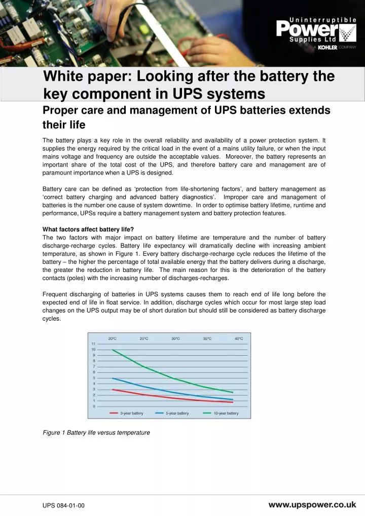
White paper: Looking after the battery the key component in UPS systems Proper care and management of UPS batteries extends their life The battery plays a key role in the overall reliability and availability of a power protection system. It supplies the energy required by the critical load in the event of a mains utility failure, or when the input mains voltage and frequency are outside the acceptable values. Moreover, the battery represents an important share of the total cost of the UPS, and therefore battery care and management are of paramount importance when a UPS is designed. Battery care can be defined as ‘protection from life-shortening factors’, and battery management as ‘correct battery charging and advanced battery diagnostics’. Improper care and management of batteries is the number one cause of system downtime. In order to optimise battery lifetime, runtime and performance, UPSs require a battery management system and battery protection features. What factors affect battery life? The two factors with major impact on battery lifetime are temperature and the number of battery discharge-recharge cycles. Battery life expectancy will dramatically decline with increasing ambient temperature, as shown in Figure 1. Every battery discharge-recharge cycle reduces the lifetime of the battery – the higher the percentage of total available energy that the battery delivers during a discharge, the greater the reduction in battery life. The main reason for this is the deterioration of the battery contacts (poles) with the increasing number of discharges-recharges. Frequent discharging of batteries in UPS systems causes them to reach end of life long before the expected end of life in float service. In addition, discharge cycles which occur for most large step load changes on the UPS output may be of short duration but should still be considered as battery discharge cycles. Figure 1 Battery life versus temperature UPS 084-01-00
Key features of a battery management system The goals of a battery management system are to protect the battery from negative environmental impacts, such as high temperature and misuse, and to avoid curtailing battery life by advanced management of battery charging and failure-preventing diagnostics. If these goals are achieved, the end user will be required to replace batteries less often, with financial and environmental benefits. A well protected and managed battery is a healthy battery, and hence it enhances the overall availability of the UPS system. Figure 2 (a) Traditional technology – the DC link is direct to the battery, which is vulnerable to all negative impacts coming from rectifier and inverter; (b) FBM – the DC link is separated by SCR from the batteries, avoiding negative impacts coming from the rectifier or inverter. It is important to note that in a UPS, the design of the DC-circuit is decisive with regard to the battery lifetime. Figure 2 compares traditional DC-circuit technology with the advanced FBM (Flexible Battery Management) technology found in PowerWAVE UPS. In the FBM design, the introduction of SCRs protects the battery by blocking all the negative impacts (AC-ripple and unwanted disturbances) that are generated by the rectifier/charger and/or inverter and traditionally reach the battery. AC-ripple free battery charging AC-ripple (Figure 3) generated by the rectifier/charger and/or inverter is the major cause of internal battery temperature increase and deterioration of battery poles. Most UPS systems in use today have DC circuits which are rich in AC-ripple. The SCR protective circuits in PowerWAVE UPSs provide battery charging which is free of AC-ripple, reducing the internal battery temperature and protecting the battery poles. In addition, an algorithm optimises the battery charge voltage to the ambient temperature. Both of these features help to prolong battery life. Figure 3 (a) Traditional battery charger rich in AC-ripple; (b) PowerWAVE battery charging is free of AC-ripple UPS 084-01-00
In traditional UPS designs where the rectifier/charger and inverter are directly linked to the battery, discharge cycles occur in the event of load jumps at the output of the UPS. These load jumps cause a decline in the DC-link voltage, and the battery will be discharged. Even though the discharge time is typically only 150msec, the high discharge currents (Figure 4a) will cause chemical reactions which will again degrade the battery poles. In PowerWAVE UPSs, the SCRs separate the battery charger from the battery, and prevent a DC-link voltage decline, or battery discharge, in the event of load jumps (Figure 4b). Figure 4 Traditionally, battery discharge occurs when a load jump occurs; (b) with no direct link between battery charger and battery, no discharge occurs Protection from misuse and inadequate charging voltages In order to proactively protect the battery from misuse or from low and high charge voltages, PowerWAVE UPSs are equipped with protective controls which are performed during the start-up procedures and during normal operation. During the system start-up, a configuration and polarity control procedure performs a cross verification between the battery parameter values configured in the UPS and the real battery voltage. An alarm is generated if there is any discrepancy. During operation, a battery fuse check is executed every 60 minutes to monitor battery presence, and a further control is executed every 30 seconds to verify that the battery voltage doesn’t exceed the permissible limits. In special circumstances, the floating voltage can be fine-tuned, depending on the number of battery blocks or whether an external battery temperature probe is connected to the UPS. In some circumstances it may be useful to adjust the minimum battery voltage in order to increase the autonomy time and define the level at which the inverter will turn off during battery operation. This value depends on the number of battery blocks, and can vary depending on the instantaneous load. Proactive battery failure detection Faulty batteries are typically discovered when the UPS transfers to battery mode in response to a utility failure and the critical load crashes. In order to help prevent such a serious situation, PowerWAVE UPSs are equipped with two kinds of battery test in order to proactively detect a faulty battery. A battery test can be performed manually or automatically at defined intervals, bearing in mind the desirability of minimising the number of discharge cycles. The test simulates a battery discharge for one minute and, the result is positive, allows a real battery discharge for one minute. At either stage the test is aborted and an alarm generated if the battery voltage falls below a pre-configured level. A deep battery discharge test safely discharges the battery completely in order to check the actual battery capacity status. This test should only be performed under manual control, and must be adaptable to parallel UPS configurations. UPS 084-01-00
Flexible configuration for least-cost autonomy Because PowerWAVE UPSs can operate with variable battery voltages, various battery configurations are allowed per UPS model. Flexibility in respect of battery capacity and the number of battery blocks can exactly match runtime requirements at lowest cost. A new level of confidence Detection of battery faults is implemented in most three-phase UPS systems. An advantage in PowerWAVE UPSs is that the FBM algorithm, which is controlled by the CPU microprocessor, continuously monitors the batteries through an automatic and adjustable test system which detects battery faults and generates an early warning. The battery charge current is adjustable and limited, and is dependent on the battery temperature. There is also battery minimum and battery maximum voltage control and limitation. Advanced FBM implemented in PowerWAVE UPSs offers the highest confidence that UPS batteries are being protected and managed in order to realise best performance and longest lifetime. A well-protected and well-managed battery is a healthy battery, enhancing the overall availability of the UPS system and critical applications. Contact Uninterruptible Power Supplies Ltd Bacchus House Calleva Park Aldermaston Berkshire RG7 8EN Phone: 0118 981 5151 Email: sales@upspower.co.uk Web: www.upspower.co.uk UPS 084-01-00