1 / 9

(四)主令控制器

(四)主令控制器. 图 1-30 主令控制器结构示意图 1 、 8- 凸轮块 2- 动触头 3- 静触头 4- 接线柱 5- 支杆 6- 转轴 7- 小轮. 第七节 常用电子式电器. 一、晶体管时间继电器. 阻容延时电路. 图 1-31 阻容延时电路分析 a )阻容延时电路基本结构形式 b) 阻容电路充电曲线. JS20 系列通电延时型继电器电路图分析. 图 1-32 JS20 系列通电延时型继电器电路图. 二、接近开关. 图 1-33 晶体管停振型接近开关方框图. 接近开关电路图分析.

Télécharger la présentation

(四)主令控制器

An Image/Link below is provided (as is) to download presentation Download Policy: Content on the Website is provided to you AS IS for your information and personal use and may not be sold / licensed / shared on other websites without getting consent from its author. Content is provided to you AS IS for your information and personal use only. Download presentation by click this link. While downloading, if for some reason you are not able to download a presentation, the publisher may have deleted the file from their server. During download, if you can't get a presentation, the file might be deleted by the publisher.

E N D

Presentation Transcript


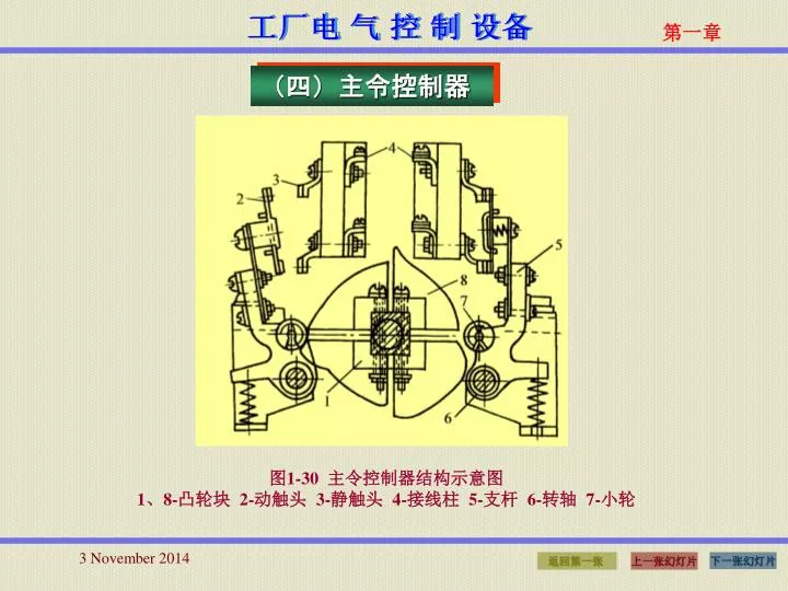
  1. (四)主令控制器 图1-30 主令控制器结构示意图 1、8-凸轮块 2-动触头 3-静触头 4-接线柱 5-支杆 6-转轴 7-小轮

  2. 第七节 常用电子式电器 一、晶体管时间继电器

  3. 阻容延时电路 图1-31 阻容延时电路分析 a)阻容延时电路基本结构形式 b)阻容电路充电曲线

  4. JS20系列通电延时型继电器电路图分析 图1-32 JS20系列通电延时型继电器电路图

  5. 二、接近开关 图1-33 晶体管停振型接近开关方框图

  6. 接近开关电路图分析 图1-34 晶体管停振型接近开关电路图

  7. 第八节 速度继电器与干簧继电器 一、速度继电器 速度继电器是根据电磁感应原理制成的,它的套有永久磁铁的轴与被控电动机的轴相联,用以接受转速信号。 图1-35 速度继电器结构原理图 1-调节螺钉 2-反力弹簧 3-常闭触头 4-动触头 5-常开触头 6-返回杠杆 7-杠杆 8-定子导条 9-定子 10-转轴 11-转子

  8. 二、干簧继电器 图1-36 干簧继电器结构原理图 a)线圈通电驱动型 b) 外磁场驱动型

  9. 第一章结束谢谢使用!

More Related