Download
1 / 20
200 likes | 333 Vues
Oceanic Thermal Energy Conversions. Group Members: Brooks Collins Kirby Little Chris Petys Craig Testa. Presentation Overview. I. Introduction What is OTEC Problem Description R-410a Overview II. Design & Analysis Design Requirements Evolution of Design

E N D
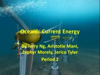
Oceanic Thermal Energy Conversions Group Members: Brooks Collins Kirby Little Chris Petys Craig Testa Group 17 Oceanic Thermal Energy Conversion Model - Lockheed Martin
Presentation Overview I. Introduction What is OTEC Problem Description R-410a Overview II. Design & Analysis Design Requirements Evolution of Design R-410a Rankine Cycle Description Component Summary & Description III. Testing and Results Circulation System Ideal Rankine Cycle Results Rankine Cycle System IV. Conclusion Group 17 Oceanic Thermal Energy Conversion Model - Lockheed Martin
Problem Statement of Project To create and design an operating Oceanic Thermal Energy Conversion model that employs a closed Rankine Cycle that utilizes R-410 A as the working fluid to illustrate the viability of OTEC power production. Group 17 Oceanic Thermal Energy Conversion Model - Lockheed Martin
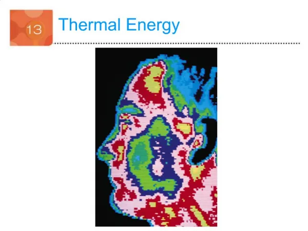
OTEC Description • Oceanic Thermal Energy Conversion • OTEC utilizes the ocean’s 20ºC natural thermal gradient between the warm surface water and the cold deep sea water to drive a Rankine Cycle • OTEC utilizes the world’s largest solar radiation collector - the ocean. The ocean contains enough energy power all of the world’s electrical needs. Group 17 Oceanic Thermal Energy Conversion Model - Lockheed Martin
Design Specifications • Our model OTEC plant should produce 100 W of power (approximate amount to power a laptop computer) • Dimensions cannot exceed 3 ft. deep x 8 ft. wide x 6 ft. tall • Must be easily portable • The model should be aesthetically pleasing as well as well organized so that individuals will be able to fully understand the inner-workings of the Rankine Cycle that powers the OTEC plant. Group 17 Oceanic Thermal Energy Conversion Model - Lockheed Martin
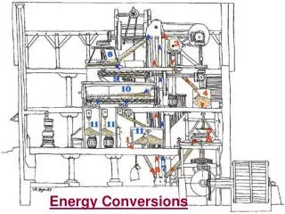
OTEC Model Diagram 4. Heat extraction from cold-water sink to condense the working fluid in the condenser. 3. Power output from turbine as the vapor isentropically expands through turbine Cycle begins again 2. Heat addition from the hot-water source to evaporate the working fluid within the heat exchanger 1. Power input to pressurize R-410a to higher pressure Group 17 Oceanic Thermal Energy Conversion Model - Lockheed Martin
R-410a Overview • R-410a and R-22 have very similar properties, but R-410a is a non-ozone depleting refrigerant • R-22 is being phased out across the globe due to the fact that is an ozone depleting refrigerant. • Every major air conditioning manufacturer in the U.S. has selected R-410a as the replacement to R-22 in all their new equipment. Group 17 Oceanic Thermal Energy Conversion Model - Lockheed Martin
R410-a P-h Diagram Rankine Cycle Group 17 Oceanic Thermal Energy Conversion Model - Lockheed Martin
Evolution of Model Designs Group 17 Oceanic Thermal Energy Conversion Model - Lockheed Martin
Analysis and Part Selection • Our analysis led us to the specs needed for part selection based on our theoretical Rankine Cycle • Calculations included heat transfer through heat exchangers, piping losses, pump sizing, and turbine power expectations Group 17 Oceanic Thermal Energy Conversion Model - Lockheed Martin
Key Part Summary – Working Fluid Pump • Hypro Piston Pump • Maximum rating of 2.20 GPM and 500 psi • Input power provided by a ¾ HP electric motor • Due to the pump ratings exceeding the specs of our system we were forced to throttle the fluid down to the appropriate pressure and flow rate Group 17 Oceanic Thermal Energy Conversion Model - Lockheed Martin
Key Part Summary – Heat Exchangers • Alfa Laval Brazed Plate Type Heat Exchangers • 4.27/6.22” x 4.37” x 20.71” • Both condenser and evaporator are same design of heat exchanger with slightly different dimensions Group 17 Oceanic Thermal Energy Conversion Model - Lockheed Martin
Key Part Summary - Turbine • Utilized the turbine side of an automotive turbocharger to produce our power output • Compressor wheel and housing were intended to be removed so that we could connect the output shaft to a generator Group 17 Oceanic Thermal Energy Conversion Model - Lockheed Martin
Finalized System Group 17 Oceanic Thermal Energy Conversion Model - Lockheed Martin
Testing and Results – Circulation Systems • Both circulation systems are functioning. • Flow rates from both pumps were measured at approximately 720 GPH • This is slightly less than calculated, but the pumps need to run continually for five hours before they are able to produce their maximum flow rates. Group 17 Oceanic Thermal Energy Conversion Model - Lockheed Martin
Ideal Rankine Cycle Results • Working fluid pump requires .57 HP to produce 2.10 GPM 300 psi. • Based on our ideal calculations, this would ideally produce 2600W of power to the turbine. • This gives our system an ideal back work ratio (ratio between work input to the pump and work output from the turbine) of .163 • Ideal efficiency of our system would be 7.3% Group 17 Oceanic Thermal Energy Conversion Model - Lockheed Martin
Testing & Results – Rankine Cycle • Based on our instrumentation (temperature gauges after both heat exchangers and pressure gauges after the pump, throttling valve, and turbine) we planned to match our system to the theoretical Rankine Cycle. • Due to our inability to find leakages within our system we were unable to test and compare our cycle to the theoretical cycle described earlier. Group 17 Oceanic Thermal Energy Conversion Model - Lockheed Martin
Conclusion • Our system is well organized and illustrates the working components of an OTEC system. • Our system sets the ground work for a miniature OTEC model, and could be made working with minimal changes. • Improvements could be made by changing to a smaller working fluid pump to decrease the work input to the system. • With the present components, our system greatly exceeds the necessary power input and output. Group 17 Oceanic Thermal Energy Conversion Model - Lockheed Martin
Group 17 Webpage http://www.eng.fsu.edu/ME_senior_design/2008/team17/Index.html Group 17 Oceanic Thermal Energy Conversion Model - Lockheed Martin
Questions & Comments? Group 17 Oceanic Thermal Energy Conversion Model - Lockheed Martin