Download
1 / 21
210 likes | 216 Vues
The Relay Controller Device (RCD) is a versatile device that allows for the configuration and operation of up to eight Form "C" relays. With a voltage range of 9 to 14 VDC, 24-hour data storage, and support for up to ten RCDs per system, this device provides reliable relay control for various applications.

E N D
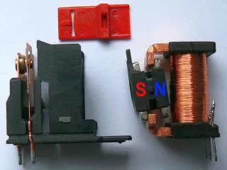
Relay Controller Device (RCD) • If additional relays are needed beyond the two that are available on the DCD, then a RCD can be employed. Each RCD has eight Form “C” relays on-board. The relays are configured using the software and have a variety of means of operation. • The Millenium Windows System can support up to ten RCD’s per SCU for a total of 80,000 relays per system.
RCD Spec’s • Voltage: 9 to 14 VDC (RCD will not operate below 9 volts) • Current: 200 ma (worst case current draw, board only) • Data Storage: 24hr minimum clock and memory backup. • Output: 8 Form “C” relays, rated at 24 VDC @ 2 amps. • Relay 0 on the RCD addressed as Device 0 is hard coded as a network communications failure output. • Tamper: Independent signal for cover tamper. • Operational Temperature: 14F to 104F (-10C to 40C).
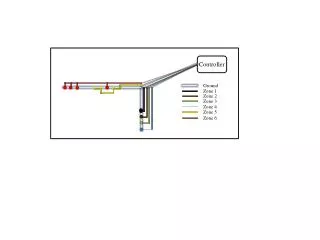
RCD Tech Notes • The inbound data trunk cable and the power cable should have some form of identification like a piece of electrical tape around the jacket to ensure that future trouble shooters know which direction the power and data source is feeding from. • The inbound and outbound shield of the trunk data cable, should be twisted together and fastened with an electrical crimp or wire nut. The shield should not connect to any terminals of the RCD PCB. • The first RCD on the network branch must have an address of “0”.
RCD Tech Notes • Inbound and outbound data trunk connections should be made on terminals 1 and 2 (respective of polarity) on the J1 connector. • Since the 12 AWG power cable is difficult to install under the terminals of the RCD, it is recommended that the inbound and outbound cables be combined with an 18 AWG pigtail which is wired to terminals 1 and 3 of the J6 connector. • The first relay on the board address as “0” is hard coded as a communications supervisory output and cannot be reprogrammed. • RCD’s are not sold with an enclosure, make you order them.