Download
1 / 26
260 likes | 358 Vues
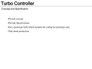
Present concept Provide Specifications Get a prototype built which includes the coding for prototype only Talk about production.

E N D
Present concept • Provide Specifications • Get a prototype built which includes the coding for prototype only • Talk about production
The Crazy Turbo Controller is a device that reads in engine sensors and provides precise and customized control of both the turbocharger and 4 accessories that a user might have. The turbocharger’s output, aka boost, will be able be to have different profiles, and then have 4 outputs that are customized and can be disabled at will. The product to be sold would consist of a LCD control head which would contains the brains, the relay & isolation box, and finally various harnesses. Following slide contains an overall simplified view.
Note: Screen Design is out of date… screen has been redesigned AND we are adding a speed sensor input for boost control.
The Components – Overview LCD/Control – Brains, display, and control. Relay/Isolation Box – All outputs from the control head need power transistors for the outputs and isolation circuits for the sensors read Pressure Sensor (MAP) is a 0 to 5 volt signal. Throttle Position Sensor (TPS) is a 0 to 5 volt signal. RPM is a pulsed signal and its frequency is of interest. SPEED is a pulsed signal and its frequency is of interest. Boost Control Solenoid is a PWM output and is a solenoid that actively controls that maximum MAP value. The settings will target a MAP value.. Accessory Outputs 1 thru 4 is a PWM output and uses the power transistor mentioned. These are just output a set PWM based on what the user wants. Switches 1 & 2 and the 5 buttons on the LCD are purely 1/0 inputs. The 5 LEDs are tied to the output signals to represent on/off and visual pwm. MiniSD contains config files.
LCD/Control Head 20x4 character White On Blue backlit display from Crystalfontz.com. The Boost Solenoid output is controlled with 4 switch able profiles. Its button switches the profile. Each accessory output has its own profile. The switch enable/disables the output manually. Current design is with a PIC16F914(?) micro controller. Able to support the currently required I/O –- serial LCD interface, MiniSD, 10 PWM outputs (5 are LED), 8 digital inputs, 2 A/D inputs, and 2 pulsed inputs. Will send 1 A/D input, 1 pulsed input, and 1 PWM output for expansion mods that are either planned or that a person might want to mod. Will also include a serial flat header for updating firmware or other functions yet to be planned. Would prefer the MiniSD provide the firmware update. DIY Relay & Isolation Box This will provide isolation between the 3 monitored sensors and the control head. This keeps shorts upstream of this box from downing the sensors/engine. Provide terminal strips for the supply and return of the 5 provided outputs. Each output supply will be a common rail 12volt. Each return/ground will be switched with a power transistor circuit with possible fly back protection. Estimation of 15 amp for each circuit/output.
MiniSD Will contain 4 configuration files for each of the 4 selectable profiles for how the boost will behave – boost_1.txt , boost_2.txt , boost_3.txt, boost_4.txt. The file name allows the processor to know which output to assign the contents to. Will contain 4 configuration files for each of the 4 accessory outputs and how they behave – output_1.txt , output_2.txt , output_3.txt , output_4.txt. The file name allows the processor to know which output to assign the contents to. The text in these files are code oriented and are loaded upon device activation.
Output Config File Code Specs Remember that the file contents are assigned to the output associated with the file name. name = string – This function assigns a descriptive name to the output the configuration file is assigned to. Display only the first 4 characters. default_state = [ on|off , enable|disable ] – on|off allows the user to define whether the output is normally on or off at startup. enable|disable allows the user to define whether the output should begin to operate when the trigger is meet, or it should require a one time enable thru it’s switch on the control head. scale_how = [ tps|rpm|map|speed , sw1|sw2 ] – tps|rpm|map|speed tells us what parameter will be used for when to scale . If sw1|sw2 is used, then that switch will be required to be activated for the output to be activated. scale_when = [floats] – an array of numbers. When a single number is used, the value will act as a greater-than or equal to trigger. When an array is used, it will be used for the x values for a lookup table for that output. output = [floats] - an array of numbers and are the duty cycles to be applied to the outputs. When a single number is used, it will define the pulse width used when the trigger condition is meet. When an array is used, it will be used for the y values for a lookup table to determine.
Output Config File Example // place a short name for the display name = “custom name” // this defines that this output is normally off, and is armed on startup. default_state = [ "off" , “enabled” ] // this causes a state change of the output from off to on (100% duty cycle) when map > 10psi scale_how = [ “map” ] scale_when = [ 10 ] output = [ 100 ]
Output Config File Example // place a short name for the display name = “custom name” // this defines that this output is normally off, and is armed on startup. default_state = [ "off" , “enabled” ] // this causes a change from off to 40% duty cycle when tps > 50%. scale_how = [ “tps” ] scale_when = [ 0.50 ] output = [ 0.40 ]
Output Config File Example // place a short name for the display name = “custom name” // this defines that this output is normally off, and is armed on startup. default_state = [ "off" , “enabled” ] // this causes a change from off to 20% duty cycle when map > 15psi // in addition, if map is 20psi, then a 35.5% duty cycle. again if map // is 30psi, then 80% duty cycle. this would be good for progressive // alky controller output since it also requires activation of sw2 to arm. scale_how = [ “map” , “sw2” ] scale_when = [15 , 19 , 21 , 24 , 30] output = [0.20 , 0.35 , 0.36 , 0.55, 0.80]
Output Config File Example // place a short name for the display name = “custom name” // this defines that this output is normally off, and is armed on startup. default_state = [ "off" , “disabled” ] // this causes a change from off to on (100 % duty cycle) when // rpm > 6500. this would be great for a shift light or something // like a non progressive n2o solenoid activation. scale_how = [ “rpm” ] scale_when = [ 6500 ] output = [ 1.0 ]
Boost Profile Config File Code Specs Remember that the file contents are assigned to the output associated with the file name. name = string – This function assigns a descriptive name to the output the configuration file is assigned to. Display only the first 5 characters. scale_how = [ tps|rpm|map|speed , sw1|sw2 ] – tps|rpm|map|speed tells us what parameter will be used for when to scale . If sw1|sw2 is used, then that switch will be required to be activated for the output to be activated. scale_when = [float] – an array of numbers. When a single number is used, the value will act as a greater-than or equal to trigger. When an array is used, it will be used for the x values for a lookup table for the previously defined parameter. boost_level = [ float ] – an array of floats and is the maximum MAP value allowed. If a single number is used, then that is the max boost used for all conditions. If an array is used, then it will define the y values for a lookup table. mix_how = tps|rpm|speed – this defines which parameter should be monitored to determine when the mix_level should be multiplied by the boost level mix_when = [ float ] – an array of numbers. This defines the x values for a lookup table in the previously defined parameter. mix_level = [ float ] – an array of numbers. This defines the y values for a lookup table which should be multiplied directly against the current boost_level. max_rate = [ float ] – a single number indicating the maximum allowable rate of climb for boost.
Boost Profile Config File Example // place a short name for the display name = “custom name” // this says that it is a standard control and has a max of 20psi boost_level = [ 20 ] // this allows you to define how quickly the boost is allowed to // ramp up. In this case, it states that you are not allowed to // climb faster then 3psi per second max_rate = [ 3 ]
Boost Profile Config File Example // place a short name for the display name = “custom name” // this is a switchable profile. max of 15psi, however we // can go to 25psi with sw1 by scaling it. scale_how = “sw1” scale_when = [ 0 , 100 ] boost_level = [ 15 , 25 ]
Boost Profile Config File Example // place a short name for the display name = “custom name” // this allows you to scale boost based on speed. scale_how = “speed” scale_when = [ 20 , 30, 40, 55, 70 ] boost_level = [ 10 , 12 , 15 , 20 , 25 ]
Boost Profile Config File Example // place a short name for the display name = “custom name” // this allows you to scale boost based on rpm just like before, but // we mix in tps to allow for further boost control. this mixer says // for example that at 80% tps that boost will be at 65% of boost_level. scale_how = “rpm” scale_when = [ 2000 , 3000, 4000, 5000, 6000 ] boost_level = [ 10 , 12 , 15 , 20 , 25 ] mix_how = “tps” mix_when = [ 0.70 , 0.80 , 0.90 , 1.0 ] mix_level = [ 0.45 , 0.65 , 0.80 , 1.0 ]
Screen Layout Including LED Bezel Buttons on edges.
Screen Layout Including LED Bezel Buttons on edges.
Screen Layout Including LED Bezel Buttons on edges. Still need to add speed sensor setup (aka frequency to speed correlation) Also need to add on cyl set if it is a waste spark cylinder setup.
Screen Layout Including LED Bezel Buttons on edges.
Screen Layout Including LED Bezel Buttons on edges.
Possible Circuit for MAP A/D – DIY Box Provision for Internal Custom MAP A/D MAP External Signal is the norm. From Megasquirt – Awaiting Approval
Possible Circuit for TPS A/D – DIY Box TPS A/D From Megasquirt – Awaiting Approval
Possible Circuit for every 2 Pulsed Output – DIY Box. 3 Total Circuits Output 1 PWM 1 PWM 2 Output 2 From Megasquirt – Awaiting Approval