Download
1 / 81
810 likes | 938 Vues
Cosc 2150: Computer Organization. Chapter 4: CPU. CPU Basics. The computer’s CPU fetches, decodes, and executes program instructions. The two principal parts of the CPU are the datapath and the control unit.

E N D
Cosc 2150:Computer Organization Chapter 4: CPU
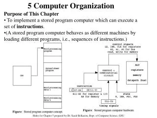
CPU Basics • The computer’s CPU fetches, decodes, and executes program instructions. • The two principal parts of the CPU are the datapath and the control unit. • The datapath consists of an arithmetic-logic unit and storage units (registers) that are interconnected by a data bus that is also connected to main memory. • Various CPU components perform sequenced operations according to signals provided by its control unit.
CPU Basics • Registers hold data that can be readily accessed by the CPU. • They can be implemented using D flip-flops. • A 32-bit register requires 32 D flip-flops. • The arithmetic-logic unit (ALU) carries out logical and arithmetic operations as directed by the control unit. • The control unit determines which actions to carry out according to the values in a program counter register and a status register.
The Bus • The CPU shares data with other system components by way of a data bus. • A bus is a set of wires that simultaneously convey a single bit along each line. • Two types of buses are commonly found in computer systems: point-to-point, and multipoint buses. These are point-to-point buses:
The Bus (2) • Buses consist of data lines, control lines, and address lines. • While the data lines convey bits from one device to another, control lines determine the direction of data flow, and when each device can access the bus. • Address lines determine the location of the source or destination of the data. • Different type of connection for different type of unit • Memory • Input/Output • CPU
Memory Connection • Receives and sends data • Receives addresses (of locations) • Receives control signals • Read • Write • Timing
Input/Output Connection(1) • Similar to memory from computer’s viewpoint • Output • Receive data from computer • Send data to peripheral • Input • Receive data from peripheral • Send data to computer
Input/Output Connection(2) • Receive control signals from computer • Send control signals to peripherals • e.g. spin disk • Receive addresses from computer • e.g. port number to identify peripheral • Send interrupt signals (control)
CPU Connection • Reads instruction and data • Writes out data (after processing) • Sends control signals to other units • Receives (& acts on) interrupts
Buses • There are a number of possible interconnection systems • Single and multiple BUS structures are most common • e.g. Control/Address/Data bus (PC) • e.g. Unibus (DEC-PDP)
What is a Bus? • A communication pathway connecting two or more devices • Usually broadcast • Often grouped • A number of channels in one bus • e.g. 32 bit data bus is 32 separate single bit channels • Power lines may not be shown
Data Bus • Carries data • Remember that there is no difference between “data” and “instruction” at this level • Width is a key determinant of performance • 8, 16, 32, 64 bit
Address bus • Identify the source or destination of data • e.g. CPU needs to read an instruction (data) from a given location in memory • Bus width determines maximum memory capacity of system • e.g. 8080 has 16 bit address bus giving 64k address space
Control Bus • Control and timing information • Memory read/write signal • Interrupt request • Clock signals
Big and Yellow? • What do buses look like? • Parallel lines on circuit boards • Ribbon cables • Strip connectors on mother boards • e.g. PCI • Sets of wires
Single Bus Problems • Lots of devices on one bus leads to: • Propagation delays • Long data paths mean that co-ordination of bus use can adversely affect performance • If aggregate data transfer approaches bus capacity • Most systems use multiple buses to overcome these problems
ISA bus • ISA (Industrial Standard Architecture) • First Open system bus architecture for PCs • 8 bit and 16 bit buses • 8 bit • 4.77 MHz, 20 address lines (1M address space) • 16 bit (introduced with the 286) • 8.33 MHz, 24 address lines (16M address space) • EISA (Extended ISA) • Introduced in 88-89 • 16/32 bit data lines, 24/32 bit address, 8.33MHz • Backward compatible with ISA, roughly twice the space of ISA
Bus Types • Dedicated • Separate data & address lines • Multiplexed • Shared lines • Address valid or data valid control line • Advantage - fewer lines • Disadvantages • More complex control • Ultimate performance
Bus Arbitration • More than one module controlling the bus • e.g. CPU and DMA controller • Only one module may control bus at one time • Arbitration may be centralised or distributed
Centralised or Distributed Arbitration • Centralised • Single hardware device controlling bus access • Bus Controller • Arbiter • May be part of CPU or separate • Distributed • Each module may claim the bus • Control logic on all modules
Timing • Co-ordination of events on bus • Synchronous • Events determined by clock signals • Control Bus includes clock line • A single 1-0 is a bus cycle • All devices can read clock line • Usually sync on leading edge • Usually a single cycle for an event
PCI Bus • Peripheral Component Interconnection • Intel released to public domain • 33/100/133/266/333+ MHz clock, independent of processor • 32 or 64 bit data and address lines (128 bit soon) • 50 lines • Supports up to 16 slots and ISA slots • Normally, 2 ISA slot, 1 of which is a “shared” slot with PCI • PCI Express x16 adapters and PCI Express x1 adapters
PCI examples • PCI 32 bit slot • AGP slot • PCI Express x16 slot • PCI Express x1 slot
PCI Bus Lines (required) • Systems lines • Including clock and reset • Address & Data • 32 time mux lines for address/data • Interrupt & validate lines • Interface Control • Arbitration • Not shared • Direct connection to PCI bus arbiter • Error lines
PCI Bus Lines (Optional) • Interrupt lines • Not shared • Cache support • 64-bit Bus Extension • Additional 32 lines • Time multiplexed • 2 lines to enable devices to agree to use 64-bit transfer
PCI Commands • Transaction between initiator (master) and target • Master claims bus • Determine type of transaction • e.g. I/O read/write • Address phase • One or more data phases
Clocks • Every computer contains at least one clock that synchronizes the activities of its components. • A fixed number of clock cycles are required to carry out each data movement or computational operation. • The clock frequency, measured in megahertz or gigahertz, determines the speed with which all operations are carried out. • Clock cycle time is the reciprocal of clock frequency. • An 800 MHz clock has a cycle time of 1.25 ns.
Clocks (2) • Clock speed should not be confused with CPU performance. • The CPU time required to run a program is given by the general performance equation: • We see that we can improve CPU throughput when we reduce the number of instructions in a program, reduce the number of cycles per instruction, or reduce the number of nanoseconds per clock cycle. We will return to this important equation in later chapters.
The Input/Output Subsystem • A computer communicates with the outside world through its input/output (I/O) subsystem. • I/O devices connect to the CPU through various interfaces. • I/O can be memory-mapped-- where the I/O device behaves like main memory from the CPU’s point of view. • Or I/O can be instruction-based, where the CPU has a specialized I/O instruction set. We study I/O in detail in chapter 7.
Memory Organization • Computer memory consists of a linear array of addressable storage cells that are similar to registers. • Memory can be byte-addressable, or word-addressable, where a word typically consists of two or more bytes. • Memory is constructed of RAM chips, often referred to in terms of length width. • If the memory word size of the machine is 16 bits, then a 4M 16 RAM chip gives us 4 megabytes of 16-bit memory locations.
Memory Organization • How does the computer access a memory location corresponds to a particular address? • We observe that 4M can be expressed as 2 2 2 20 = 2 22 words. • The memory locations for this memory are numbered 0 through 2 22 -1. • Thus, the memory bus of this system requires at least 22 address lines. • The address lines “count” from 0 to 222 - 1 in binary. Each line is either “on” or “off” indicating the location of the desired memory element.
Memory Organization • Physical memory usually consists of more than one RAM chip. • Access is more efficient when memory is organized into banks of chips with the addresses interleaved across the chips • With low-order interleaving, the low order bits of the address specify which memory bank contains the address of interest. • Accordingly, in high-order interleaving, the high order address bits specify the memory bank. The next slide illustrates these two ideas.
Memory Organization Low-Order Interleaving High-Order Interleaving
Memory Organization • Example: Suppose we have a memory consisting of 16 2K x 8 bit chips. • Memory is 32K = 25 210 = 215 • 15 bits are needed for each address. • We need 4 bits to select the chip, and 11 bits for the offset into the chip that selects the byte.
Memory Organization • In high-order interleaving the high-order 4 bits select the chip. • In low-order interleaving the low-order 4 bits select the chip.
Data Flow (Instruction Fetch) • Depends on CPU design • In general: • Fetch • PC contains address of next instruction • Address moved to MAR • Address placed on address bus • Control unit requests memory read • Result placed on data bus, copied to MBR, then to IR • Meanwhile PC incremented by 1 • IR is examined
Indirect Cycle • Added to fetch • May require memory access to fetch operands • Indirect addressing requires more memory accesses • Can be thought of as additional instruction subcycle The next slide shows a flowchart of this process.
Data Flow (Data Fetch) • If indirect addressing, indirect cycle is performed • Right most N bits of MBR transferred to MAR • Control unit requests memory read • Result (address of operand) moved to MBR
Data Flow (Execute) • May take many forms • Depends on instruction being executed • May include • Memory read/write • Input/Output • Register transfers • ALU operations • In other words: • do what the instruction says to do.