Download
1 / 38
380 likes | 578 Vues
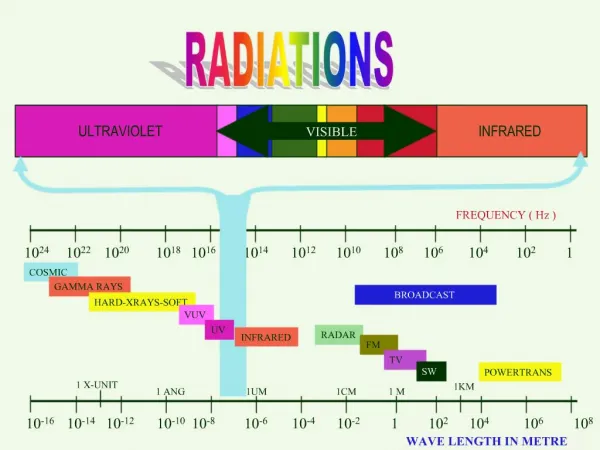
The Infrared Array Camera (IRAC) on the Spitzer Space Telescope. Joseph Hora & the IRAC instrument team Harvard-Smithsonian Center for Astrophysics. Outline. overall behavior of detectors relative to pre-flight predictions, plus: a.) short wavelength response/qe issue;

E N D
The Infrared Array Camera (IRAC) on the Spitzer Space Telescope Joseph Hora & the IRAC instrument team Harvard-Smithsonian Center for Astrophysics
Outline • overall behavior of detectors relative to pre-flight predictions, plus: • a.) short wavelength response/qe issue; • b.) cosmic ray effects; • c.) latent images and their mitigation • d.) implications of operation without a shutter; • e.) effects when detectors are first turned on • f.) status of absolute calibration
Infrared Array Camera Top-Level Requirements (Actual Performance) (Predicted) Channel Center Total Angular Field of Relative Broadband No. Wavelength Bandwidth Pixel Size View Photometric Sensitivity (microns) (%) (arcsec.) (arcmin.) Accuracy (5 sigma/200sec.) (max error %) (mJy) 1 (InSb) 3.6(3.55) 20 (21)1.2(1.210)5.12 x 5.12(5.17 x 5.17)2.0(<2.0)4.6(2.5) (2.0) 2 (InSb) 4.5(4.52) 23(23)1.2(1.207)5.12 x 5.12(5.15 x 5.15)2.0(<2.0)6.1(4.5) (4.2) 3 (Si:As) 5.8(5.70) 25(26)1.2(1.213)5.12 x 5.12(5.18 x 5.18) 2.0(<2.0)30(15.5) (27.5) 4 (Si:As) 8.0(7.92) 38 (37)1.2(1.209)5.12 x 5.12(5.16 x 5.16)2.0(<2.0)45 (25.0) (34.5) IRAC Description • IRAC is a simple 4-channel camera with fixed broad-band filters centered at 3.6, 4.5, 5.8 and 8.0 mm • Four 256 x 256 pixel detector arrays (2 InSb, 2 Si:As). • simultaneous readout of all four arrays • Two nearly adjacent fields of view (5.2 x 5.2 arcmin), viewed in pairs (3.6, 5.8 μm and 4.5, 5.8 μm).
IRAC DETECTOR CHARACTERISTICS • IRAC ARRAY PERFORMANCE IS EXCELLENT. • ARRAYS BUILT BY RAYTHEON/SBRC. (37) (55)
QE Issue • ISA 81959 was entered on 9/23/2003 based on results obtained during the first few campaigns in IOC. IRAC throughput was measured in campaigns B, C, D, and E using six calibrator stars. The in-band fluxes of these stars, all of which are K-giants, were estimated for the IRAC bands using existing spectra of K-giants scaled by ground based optical/near-IR photometry of the calibrator stars. Although the measured throughputs for IRAC channels 1 and 2 were consistent with pre-launch measurements, the values for channel 3 and 4 were consistently only 45% and 61% of the pre-launch predicted throughputs, respectively.
Si:As QE Ch4 Ch3
Flux Scattering Out of Aperture Graph of the Ratio of Total Flux in all Bands to Total Source Flux versus wavelength. The total flux in all other pixels (not shown in graph) is 130% of the Ratio of Band to Source at all wavelengths
IRAC ARTIFACTS • Multiplexer bleed, banding and column pulldown
Residual Images Normal residuals – after exposure to bright source, next image it is <0.5% of bright source, decays exponentially
NEW: Persistent images: long-lived • During IOC, we learned that very bright sources leave persistent images that can last >7 hrs in channels 1 and 4 • Lab tests confirmed channel 1 persistence due to known array defect; channel 4 under study • Preventive mitigation: • Every 12 hours, anneal ch1&4 • Anneals remove latents; implemented 1st campaign • NEW: Move observations containing K<3 stars before anneal; implemented 3rd campaign (by hand) Channel 4 “dark” hours after bright star
Ch1 Downlink Residuals Frames after an anneal showing residuals
Ch1 Downlink Residuals First (left) and last (right) exposure of 6678272 . Separated by 1.5 hours. The actual latent image. This is the derived image of whatever the array was staring at.
Residual Removal through anneals Ch1 Ch4
Routine Anneals Cernox sensors saturated, T~30K
Shutterless Operation • Basic result is that instrument is stable, but calibrations take significantly more time • Dark frame stability is extremely good • No variations in dark pattern seen • Short-term variations from residuals present • Long-term drifts seen in baseline level – zodi background changes? • Calibration relies on standard sources, no quick pixel-wise check possible • Flat fields measured on sky – no quick measurement possible • Linearity measurement in flight difficult for Ch. 1 and 2
Calibration Stability The scatter between standards is consistent with the 2%-3% uncertainty expected in the stellar models. The relative calibration stability for a particular standard star over the six campaigns is in the 1%-2% range for all channels.
Effects of Anneals on Arrays Without anneal With anneal
Conclusions: overall behavior of detectors relative to pre-flight predictions – no changes, QE lower than expected, Point/extended source issue, but could have known • a.) short wavelength response/qe issue – scattering inside array, • b.) cosmic ray effects – 4-8 CR pixels/sec • c.) latent images and their mitigation • Unexpected downlink and long-term Ch4 latents, but are removed with anneals
Conclusions (2): • d.) implications of operation without a shutter • Arrays stable, ground-based calibration valid, • In-flight calibrations more time consuming or not practical • e.) effects when detectors are first turned on • Dark current instability in first ~30 min • Stellar calibration constant • f.) status of absolute calibration • Variations between stars 2-3% in all channels
IRAC IMAGE QUALITY 1 2 3 4 30″ 5′ FWHM (″) 1.43 1.44 1.49 1.71
IRAC ARTIFACTS Stray light (point sources and diffuse light)