Download

1 / 58
580 likes | 771 Vues
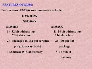
80386DX. Programming Model. The basic programming model consists of the following aspects: Registers Instruction Format Addressing Modes Data types Memory Organization and Segmentation Interrupts and Exceptions. Memory Organization and Segmentation. Introduction.

E N D
Programming Model • The basic programming model consists of the following aspects: • Registers • Instruction Format • Addressing Modes • Data types • Memory Organization and Segmentation • Interrupts and Exceptions
Introduction • Memory is divided into bytes, words and dwords. • Words are stored in two consecutive bytes and dwords in 4 consecutive bytes • It supports larger units of memory: pages and segments. • Segmentation: Memory is divided into one or more variable length segments, which can be swapped to disk or shared between programs.
Introduction • Paging: Memory is organized into one or more 4KB pages. • Segmentation and Paging can be combined to gain advantages of both systems. • Segmentation is used for organizing memory in logical modules (for application program) • Pages are useful for system programmer for managing physical memory of system.
Address Spaces • 80386DX has three distinct address spaces: • Logical(Virtual) Address: • It consists of a selector and an offset • Selector : contents of segment register • Offset : Effective address (sum of base, index and displacement) • Each task has maximum of 16K selectors (214) and offset can be 4GB(232) to give a total of 246 or 64TB
Address Spaces • Linear Address • Segmentation unit translates logical address space into 32-bit linear address space. • If there is no paging linear address will be the physical address • Physical Address • Paging unit translates linear address space to physical address space • It is what appears on address pins.
Operating Modes • The Intel 386DX has two modes of operation • Real (Real Address) Mode and • Protected Mode (Protected Virtual Address Mode) • Real Mode: • It works as a very fast 8086 with 32-bit extensions. • It is required to set up the processor for protected mode
Operating Modes • Protected Mode: • It provides access to sophisticated memory management, paging and privilege capabilities of the processor
Real Mode Architecture • It has same base architecture as 8086 • When a processor is reset, it is initialized in real mode. • It sets up the processor for Protected Mode. • The segment size in real mode is 64KB • The maximum memory size is 1MB • Only address lines A2-A19 are active
Real Mode Architecture • Since paging is not allowed, the physical address is same as linear. • Physical Address is formed by adding contents of segment register shifted left by 4 bits to an effective address. • This results in a physical address from 00000000 to 0010FFEF (FFFF0+FFFF) • Real mode segments always start on 16-byte boundaries since they are left shifted.
Protected Mode UQs : Draw protected mode address translation mechanism of 80386 and explain segment translation in detail.(2)
Protected Mode Architecture • It provides an increased address space (64TB virtual memory) and different addressing mechanism.
Virtual Memory • It is implemented using the physical memory that the CPU can directly access and the secondary memory that is used as a storage for data and program. • It allows only part of the program needs to be in memory for execution
Virtual Memory • In case of huge programs, they are divided into smaller segments or pages (arranged in appropriate sequence) and are swapped in or out of primary memory as per the requirement for execution of complete program. • These segments or pages are associated with a descriptor which contains information about this segment or page
Virtual Memory • A set of such descriptors (called Descriptor Table) arranged in a proper sequence describes the complete program. • In case of multiprogramming environment, many of such descriptor table may be available in the system at an instant of time • Descriptor Table are prepared and managed by the operating system.
Virtual Memory • For different types of program segments, there may be different types of descriptors • The descriptors are automatically referred to by the CPU when a segment register is loaded.
Selector (Segment Register) • A selector in protected mode has 3 fields: • TI (Table Indicator): Local or Global Descriptor Table Indicator • Index(Descriptor Entry Index ): Selects one of 8K descriptors • RPL (Requestor Privilege Level): allows testing of selector’s privilege attributes • Level 0: Most Privilege Level • Level 3: Least Privilege Level 22
Selector 23
Descriptor Tables • It defines all the segments used in x86 system • There are 3 types of table: • Global Descriptor Table(GDT) • Local Descriptor Table(LDT) • Interrupt Descriptor Table(IDT) • All tables are variable length memory arrays • They can range in size from 8 bytes to 64KB (213 x 23) (3 bits are implied as descriptor size is fixed)
Descriptor Tables • Each table can hold up to 8192(213) 8-byte descriptors. • The table has registers associated with them named GDTR, LDTR and IDTR which hold the 32-bit linear base address and 16-bit limit of each table. • These tables are manipulated by the OS using privileged instructions.
Global Descriptor Table • Every Intel386 DX system contains a GDT. • GDT contains descriptors which are possibly available to all of the tasks in the system. • GDT contains code and data segments used by the operating systems and task state segments and descriptors for the LDTs in a system • The first slot of GDT corresponds to the null selector and is not used.
Global Descriptor Table • Global Descriptor Table Register
Local Descriptor Table • LDTs contain descriptors which are Task Specific. • LDT may contain only code, data, stack, task gate and call gate descriptors. • LDTs isolates a given task's code and data segments from the rest of the OS. • The visible portion of LDT register contains only a 16-bit selector. • This selector refers to a Local Descriptor Table Descriptor in the GDT.
Interrupt Descriptor Table • The IDT contains the descriptors which point to the location of up to 256 interrupt service routines. • Every interrupt used by a system must have an entry in the IDT. • IDT entries are referenced via INT instructions, external interrupt vectors and exceptions.
Descriptors • The object to which the segment selector points to is called a descriptor. • Descriptors are 8 byte quantities which contain attributes about a given segment.
Descriptors • These attributes include : • 32-bit base linear address of the segment, • 20-bit length and granularity of the segment, • the protection level, • read, write or execute privileges, • the default size of the operands (16-bit or 32-bit) • the type of segment.
General Format of a Descriptor • Base: Base Address of the segment. • Limit: Length of the Segment
General Format of a Descriptor • G(Granularity) bit: It indicates whether the segment is page addressable • G = 0 byte granular (max 1MB) segment size may be 1, 2, ..., 220 bytes • G = 1 page granular (max 4GB) segment size may be 1 × 212,2 × 212, ...,220 ×212 bytes
General Format of a Descriptor • D(Default Operand Size): It indicates default length for operands and effective addresses. • D = 1 32-bit operand • D = 0 16-bit operand
General Format of a Descriptor • AVL(Available) bit: This field specifies whether the descriptor is available to the user or to the operating system.
Protected Mode Addressing Mechanism • 80386 transforms logical addresses (i.e., addresses as viewed by programmers) into physical address (i.e., actual addresses in physical memory) in two steps: • Segment translation: a logical address (segment selector and offset) is converted to a linear address. • Page translation: a linear address is converted to a physical address.(optional) • These translations are performed in a way that is not visible to applications programmers.
Paging Unit • Paging is used for virtual memory multitasking operating system. • Pages are fixed size portions of the program module or data • The complete task need not be in physical memory at any time and only a few pages are required. • Hence the remaining space can be allocated for other tasks and thus multitasking can be achieved
Paging Mechanism • Intel386DX uses a two level table mechanism to convert linear address to physical address. • Paging unit handles every task in terms of 3 components namely: • 1. Page Directory • 2. Page Table • 3. Page Frame (page itself) • Page size of Intel 386DX is 4KB
Page Descriptor Base Register • CR2 is used to store the 32-bit linear address of page fault. • CR3 (Page Directory Physical Base Address Register) stores the physical starting address of Page Directory.
Page Descriptor Base Register • The lower 12 bits of CR3 are always zero to ensure that the Page Directory is always page aligned • A move operation to CR3 automatically loads the Page Table Entry caches and a task switch through a TSS changes the value of CR0.
Page Directory • It is at the most 4KB in size and allows upto 1024 (only 10bits from linear address) entries are allowed. • The upper 10 bits of the linear address are used as an index to corresponding page directory entry • Page directory entry points to page tables.
Page Tables • Each Page Table is 4KB and holds up to 1024 Page Table Entries(PTE). • PTEs contain the starting address of the page frame and statistical information about the page. • The 20 upperbit page frame address is concatenated with the lower 12 bits of the linear address to form the physical address. • Page tables can be shared between tasks and swapped to disks.
Page Table Entry • P(Present)Bit: indicates if the entry can be used in address translation. P-bit of the currently executed page is always high. • A (Accessed) Bit: It is set before any access to the page.
Page Table Entry • D (Dirty) bit: It is set before a write operation to the page is carried out. The D bit is undefined for PDEs. • OS Reserved Bits: They are defined by the operating system software. • U/S (User/Supervisor)Bit and R/W (Read/Write) Bit: They are used to provide protection. They are decoded as