Download
1 / 19
200 likes | 306 Vues
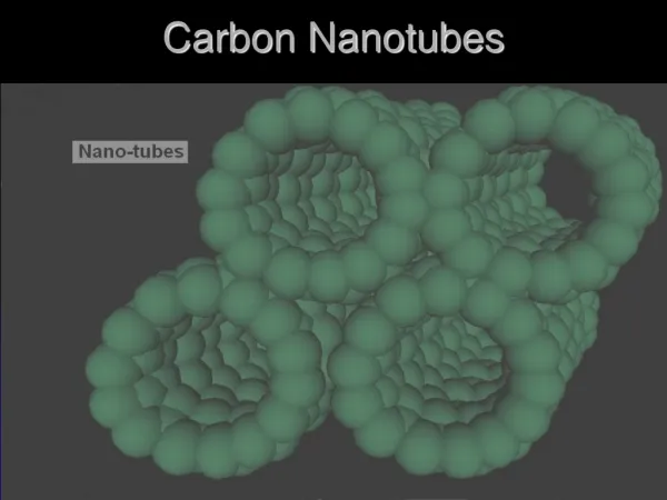
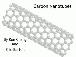
Image-potential States in Carbon Nanotubes. PLAN. Introduction Carbon nanotube Image states Time-resolved two photon photoemission Calculation of image potential states Model potential Binding energies for SWNT and MWNT Nanotube bundles Experimental setup Pump-probe optics

E N D
PLAN • Introduction • Carbon nanotube • Image states • Time-resolved two photon photoemission • Calculation of image potential states • Model potential • Binding energies for SWNT and MWNT • Nanotube bundles • Experimental setup • Pump-probe optics • Electron Spectrometer • Nanotube samples
Historical Overview Synthesis of a Carbon nanotube 1991 S. Iijima, Nature (London) 354, 56 (1991) 1985 Discovery of fullerenes "C-60 - Buckminsterfullerene." H. W. Kroto, J. R. Heath, S. C. Obrien, R. F. Curl and R. E. Smalley. Nature, 318, 162-163 (1985).
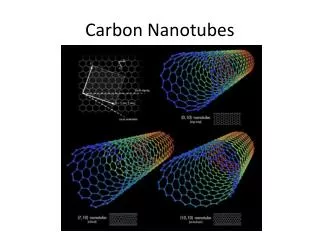
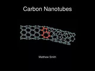
Nanotube geometries Single walled nanotube Multi walled nanotube
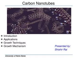
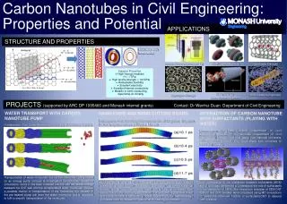
Potential Applications of Carbon nanotubes Field Emission Energy Storage Molecular Electronics Biomedical Applications Thermal Materials Structural Composites Fibers and Fabrics
Image-potential states Negative charge Positive charge -0.5 eV
Tubular Image States In Carbon nanotubes B. E. Granger et al., Phys. Rev. Lett. 89, 135506 ( September 2002)
Time-Resolved TPPE Our simulation for a SWNT 1.5 eV Projected probe effect Vacuum level n=1 4.52eV Projected pump effect Fermi level DOS For (9,9) SWNT Occupied bands
Time-Resolved TPPE Binding energy of the state Phase of the wave function 2-D projection of an electron momentum
Image-potential states with l<6 Dependence of image-potential states on the nanotube diameter Image-potential states in Multi walled nanotubes Lower binding energies Centrifugal barrier Isolated nanotubes Localize closer to a nanotube Binding energies Easier to produce More accessible experimentally Low-angular momentum image potential states Tubular image states
VTotal VJellium inner nanotube outer nanotube Model potential
SWNT MWNT
Nanotube diameter effects • Diameter distribution • SWNT 0.8-1.4 nm • MWNT 5-100 nm
Nanotube bundles Formation of the image potential well between nanotubes Veff (eV) Effective potential (eV) 2.3 Y, (nm) 0.6 X, (nm) -3.0 3.0 Tendency of SWNTs to form bundles (ropes)
Experimental setup: Laser system Harmonics separator Delay stage 3hω Beam Splitter λ/2 f = 15 cm f = 17.5 cm CCD
Electron Spectrometer 0 V 300 V Double magnetic shielding Backgammon detector
Nanotube samples 10 mm 0.2 mm 10 mm Bucky paper