Download
1 / 20
200 likes | 339 Vues
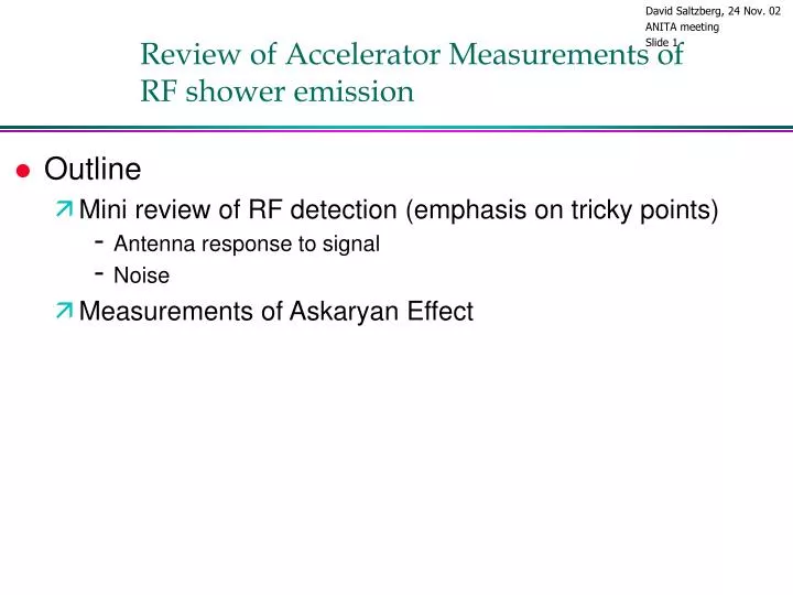
Review of Accelerator Measurements of RF shower emission. Outline Mini review of RF detection (emphasis on tricky points) Antenna response to signal Noise Measurements of Askaryan Effect. Basic Anatomy of an Antenna +Receiver. balun. E.

E N D
Review of Accelerator Measurements of RF shower emission • Outline • Mini review of RF detection (emphasis on tricky points) • Antenna response to signal • Noise • Measurements of Askaryan Effect
Basic Anatomy of an Antenna +Receiver balun E Rr=“radiation resistance”= impedance looking into back of balun V E Rr=50 or 75 (typical) coax cable E field Z0 = 377/n Balun impedance matches AND isolates outside of cable shield from radiator, BUT is difficult to make broad-band Rr=50 or 75 (typical)
Electric fields and Antennas • View I: Electric fields & Effective height • E field measured in V/m • Antenna described by effective height, heff, where • Careful, V is the “open circuit” voltage, i.e. if antenna is looking into infinite impedance. For a matched load, divide by 2
Electric fields and Antennas • View 2: Pointing Flux and Effective Aperture • S = E2/Z (E is instantaneous E(t)…careful factors of 2), where Z0=377 in free space (W/m2) • P=A*S • In media, Z0= 377 * • Power delivered by antenna into a matched load is called “effective aperture”. (assuming no ohmic losses) • Careful, note difference in defintion wrt heff • If load is known, can go between two views:
Noise • R.F.I. : Radio Frequency Interference, typically manmade. • If impulsive, could mimic signals without increasing system temperature • Even if not impulsive, can raise system temperature • If narrow band, can be removed by notch filtering (online) or by making a cut on signal duration (offline). • Even “broadband” RFI can usually be removed offline by cutting on duration • Do not expect EXTREMELY broadband (100-1000 MHz) and short duration from RFI. • Even if not impulsive, can raise system temperature
Noise • Thermal noise • Broadband and is ultimate background since can look like signal • If antenna aperture is filled by source at temperature T, expect power delivered to matched load to be P=kB*T*B, where B=bandwidth • Gives V fluctuating as Gaussian with Vrms=sqrt(P*R) where R is input impedance of detector (typ. 50). This is a bit more complex when bandwidth≠100% • 290K filling aperture, connected to matched load: • P=-174 dBm/Hz • Vrms=0.45 nV/sqrt(Hz) if 50 system
Recommended Reading • J. Kraus, “Antennas, 2nd ed”, esp. chapter 2 • C. Balanis, “Antenna Theory” • ARRL “The Antenna Book” • M. Schwartz, “Information Transmission, Modulation, and Noise” (you can skip the part on vacuum tubes!) • Horowitz & Hill (amplifiers, noise…)
Lunacee II and III(July 2000 and June 2002) Askaryan Experiments at SLAC: SLAC/FFTB 30 GeV e- < 1mm bunch size 1-3%X0 radiators up to 1019 eV in ’s Only photons leave the vacuum window no TR 30 GeV linac FFTB radiators <E>=4 GeV 30 GeV e- e- & e- to dump
Lunacee II and III • SLAC, Final Focus Testbeam • Al Odian contacted us after seeing Lunacee-I preprint • Bremsstrahlung photons from 28 GeV electrons • Very small beamsize (<<1mm) • Real charge excess develops • photon beam so no Transition Radiation
Two SLAC runs June 2002 July 2000
Target Geometry Lunacee II Lunacee III, similar geometry but built with salt bricks
Bandlimitted pulses E.g., 1.7 to 2.6 GHz With radiator out, saw mV/m fields. In general, t ~ 1/BW # cycles ~ 1/ frac. BW
1. V/m/MHz at 1m 0.1 0.01 Absolute field emission check Also took data in 2002 run to check coherence out to ~12 GHz. To be analyzed
Shock wave Speed of radio propagation in sand=0.6 c Measured speed = (1.00.1)c CR shock wave Shock wave at Cos-1(1/n)~51O ``Snelled’’ to 29O
T.I.R. • Anita needs to see signals that are transmitted from ice to vacuum (chance of total internal reflection) • Tested at Lunacee-II, from sand to air, and saw a 36 dB suppression • Antarctica’s firn layer should help somewhat. • Still will be loss due to Fresnel Coeff.
Transition Radiation • TR is made whenever a charged particle crosses a dielectric boundary • Closely related to CR and all the coherence arguments of Askaryan hold • In Lunacee –I sent a 15 MeV electron beam through a foil. Found X10 disagreement with prediction. Perhaps because we were not monitoring beam at its last stage • Lunacee –III created an electron beam from the SLAC photon beam using a lead brick & aluminum plate. Calcuated E field (0.28 V/m) was consistent with observed (0.31 V/m).
Summary & ideas • Askaryan effect is established (or why would you be here?) • Other tools we may need • User module to provide parameterized E-fields to MC simulations • Better parameterization of angular distribution of emission (including airy peaks) • Antenna design code • Digital signal processing code • Apply to understanding transmissivity of Firn (hard to do experimentally?)