Download
1 / 64
640 likes | 745 Vues
Combinational Circuit Design: Practice. Outline. Derivation of efficient HDL description Operator sharing Functionality sharing Layout-related circuits General circuits. Derivation of efficient HDL description. Think “H”, not “L”, of HDL Right way:

E N D
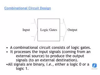
Combinational Circuit Design: Practice Chapter 7
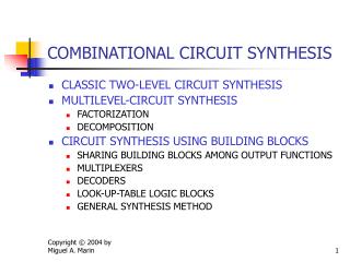
Outline • Derivation of efficient HDL description • Operator sharing • Functionality sharing • Layout-related circuits • General circuits Chapter 7
Derivation of efficient HDL description • Think “H”, not “L”, of HDL • Right way: • Research to find an efficient design (“domain knowledge”) • Develop VHDL code that accurately describes the design • Wrong way: • Write a C program and covert it to HDL Chapter 7
Sharing • Circuit complexity of VHDL operators varies • Arith operators • Large implementation • Limited optimization by synthesis software • “Optimization” can be achieved by “sharing” in RT level coding • Operator sharing • Functionality sharing Chapter 7
An example 0.55 um standard-cell CMOS implementation Chapter 7
2. Operator sharing • “value expressions” in priority network and multiplexing network are mutually exclusively: • Only one result is routed to output • Conditional sig assignment (if statement) sig_name <= value_expr_1 when boolean_expr_1 else value_expr_2 when boolean_expr_2 else value_expr_3 when boolean_expr_3 else . . . value_expr_n; Chapter 7
Selected sig assignment (case statement) with select_expression select sig_name <= value_expr_1 when choice_1, value_expr_2 when choice_2, value_expr_3 when choice_3, . . . value_expr_n when choice_n; Chapter 7
Example 1 • Original code: r <= a+b when boolean_exp else a+c; • Revised code: src0 <= b when boolean_exp else c; r <= a + src0; Chapter 7
Area: 2 adders, 1 mux Delay: Area: 1 adder, 1 mux Delay: Chapter 7
Example 2 • Original code: process(a,b,c,d,...) begin if boolean_exp_1 then r <= a+b; elsif boolean_exp_2 then r <= a+c; else r <= d+1; endif end process; Chapter 7
Revised code: process(a,b,c,d,...) begin if boolean_exp_1 then src0 <= a; src1 <= b; elsif boolean_exp_2 then src0 <= a; src1 <= c; else src0 <= d; src1 <= "00000001"; endif; endprocess; r <= src0 + src1; Chapter 7
Area:2 adders, 1 inc, 2 mux Area: 1 adder, 4 mux Chapter 7
Example 3 • Original code: with sel select r <= a+b when "00", a+c when "01", d+1 whenothers; • Revised code: with sel_exp select src0 <= a when "00"|"01", d whenothers; with sel_exp select src1 <= b when "00", c when "01", "00000001" whenothers; r <= src0 + src1; Chapter 7
Area: 1 adder, 2 mux Area:2 adders, 1 inc, 1 mux Chapter 7
Example 4 • Original code: process(a,b,c,d,...) begin if boolean_exp then x <= a + b; y <= (others=>'0'); else x <= (others=>'1'); y <= c + d; endif; end process; Chapter 7
Area:2 adders, 2 mux Chapter 7
Revised code: begin if boolean_exp then src0 <= a; src1 <= b; x <= sum; y <= (others=>'0'); else src0 <= c; src1 <= d; x <= (others=>'1'); y <= sum; endif; end process; sum <= src0 + src1; Chapter 7
Area: 1 adder, 4 mux • Is the sharing worthwhile? • 1 adder vs 2 mux • It depends . . . Chapter 7
Summary • Sharing is done by additional routing circuit • Merit of sharing depends on the complexity of the operator and the routing circuit • Ideally, synthesis software should do this Chapter 7
3. Functionality sharing • A large circuit involves lots of functions • Several functions may be related and have common characteristics • Several functions can share the same circuit. • Done in an “ad hoc” basis, based on the understanding and insight of the designer (i.e., “domain knowledge”) • Difficult for software it since it does not know the “meaning” of functions Chapter 7
e.g., add-sub circuit Chapter 7
Manual injection of carry-in: Append an additional bit in right (LSB): Chapter 7
e.g., sign-unsigned comparator Chapter 7
Binary wheel Chapter 7
Observation: • Unsigned: normal comparator • Signed: • Different sign bit: positive number is larger • Same sign: compare remaining 3 LSBsThis works for negative number, too!E.g., 1111 (-1), 1100 (-4), 1001(-7) 111 > 100 > 001 • The comparison of 3 LSBs can be shared Chapter 7
e.g., Full comparator Chapter 7
Read 7.3.3 and 7.3.5 Chapter 7
4. Layout-related circuits • After synthesis, placement and routing will derive the actual physical layout of a digital circuit on a silicon chip. • VHDL cannot specify the exact layout • VHDL can outline the general “shape” Chapter 7
Silicon chip is a “square” • “Two-dimensional” shape (tree or rectangular) is better than one-dimensional shape (cascading-chain) • Conditional signal assignment/if statement form a single “horizontal” cascading chain • Selected signal assignment/case statement form a large “vertical” mux • Neither is ideal Chapter 7
e.g., Reduced-xor circuit Chapter 7
Comparison of n-input reduced xor • Cascading chain : • Area: (n-1) xor gates • Delay: (n-1) • Coding: easy to modify (scale) • Tree: • Area: (n-1) xor gates • Delay: log2n • Coding: not so easy to modify • Software should able to do the conversion automatically Chapter 7
e.g., Reduced-xor-vector circuit Chapter 7
Direct implementation Chapter 7
Functionality Sharing Chapter 7
Direct tree implementation Chapter 7
“Parallel-prefix” implementation Chapter 7
Comparison of n-input reduced-xor-vector • Cascading chain • Area: (n-1) xor gates • Delay: (n-1) • Coding: easy to modify (scale) • Multiple trees • Area: O(n2) xor gates • Delay: log2n • Coding: not so easy to modify • Parallel-prefix • Area: O(nlog2n) xor gates • Delay: log2n • Coding: difficult to modify • Software is not able to convert cascading chain to parallel-prefix Chapter 7
e.g., Shifter (rotating right) • Direct implementation Chapter 7