Download
1 / 20
200 likes | 651 Vues
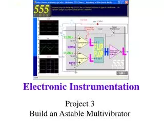
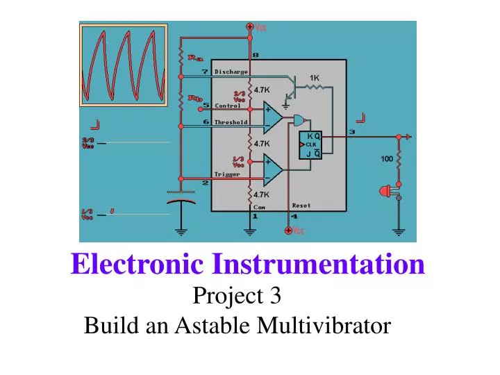
Project 3 Build an Astable Multivibrator. Purpose. The purpose of this project is to build an Astable multivibrator without the 555-timer chip. This means you will have to assemble your own components to mimic the behavior of the inside of the chip.

E N D
Purpose • The purpose of this project is to build an Astable multivibrator without the 555-timer chip. • This means you will have to assemble your own components to mimic the behavior of the inside of the chip. • You will create a PSpice simulation and a working circuit. • You will then determine how to modify the 555 timer chip model so that it cycles over a different part of the capacitor charge curve. • You will modify your PSpice simulation and circuit to demonstrate that your new model works as predicted. Electronic Instrumentation
The Animation Animation applet Your initial design will be a PSpice simulation and working circuit based on this animation. Electronic Instrumentation
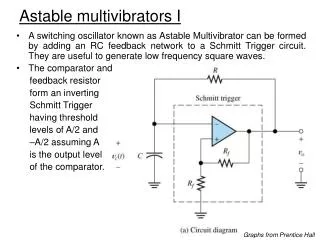
Block Diagram • Circuits are often represented by block diagrams that show the flow of the signal between different functional blocks. • Above is a block diagram of the astable multivibrator. Electronic Instrumentation
Components in each Block C A H E G B D F Electronic Instrumentation
Components in each Block A: R-R-C Combination B: Voltage Divider C: Threshold Comparator D: Trigger Comparator E: Reset Logic Chip (NAND gate) F: J-K Flip Flop G: LED Circuit H: Transistor Circuit Electronic Instrumentation
How does the Astable Multivibrator work? What makes this circuit generate a string of pulses? This is discussed in detail in the experiment 7 notes. Animation applet Electronic Instrumentation
How does the Astable Multivibrator work? These equations determine the characteristics of your output pulses based on the values you choose for R1, R2 and C1. Electronic Instrumentation
How does the Astable Multivibrator work? • The frequency of the pulses and their duty cycle are dependent upon the RC network values. • The capacitor C charges through the series resistors R1 and R2 with a time constant of tON = (R1 + R2)C1. • The capacitor discharges through R2 with a time constant of tOFF = R2C1 Electronic Instrumentation
Where do the equations come from? The equations that determine the on and off time of the output pulses are based on the charge and discharge time of the capacitor. The capacitor equations are: charging discharging Electronic Instrumentation
Relating charge equations to time How much time should it take to charge between 1/3 and 2/3 of V0? Time to charge up to 2/3V0 is: Electronic Instrumentation
Initial Design PSpice • Build the PSpice circuit and look at the signals at the input and output of each block in the diagram. • ignore timing errors from the simulation • Use the cursors to mark important voltage levels and times • high and low on digital signals • important points on analog signals (like 1/3 and 2/3 of Vcc) • on and off time of the pulses Electronic Instrumentation
Initial Design Protoboard • Build the circuit on your protoboard • tie pin 13 of flip flop to 5V • don’t forget to put power on the digital chips • add a bypass capacitor • use a 1k pot as a variable pull-down resistor • set clock to 100k hertz • Take pictures with Agilent • Use voltage and time features of scope • Use the cursors on the scope • Make sure you have actual numerical values on the pictures that you take Electronic Instrumentation
Useful Scope Features VOLTAGE * Vave (DC) * Vp-p (AC) TIME * Freq * Period * Duty Cy CURSOR * T1, T2, DT * V1, V2, DV * moves cursors Electronic Instrumentation
Final Design • How would you modify the inside of the timer to make it charge between ¼VCC and ¾ VCC? • What are the new equations for TON and TOFF? • What are the new on and off times for the pulses in your circuit? • Modify the PSpice and the circuit on your protoboard and show that your results are consistent with those predicted by the equations. Electronic Instrumentation
Project Report • Introduction • What is the objective of the project? • At least two relevant topics • Theory • Describe the function of the components in the circuit • How does the multivibrator work? Give details. • Where do the equations for TON and TOFF come from? • What should TON and TOFF be for the circuit you are building? Electronic Instrumentation
Project Report • Initial Design • PSpice simulation, plots, and discussion • Protoboard implementation, pictures, and discussion • comparison of voltages and times • PSpice • Protoboard • Theory Electronic Instrumentation
Project Report • Final Design • Determine how to change circuit. • Come up with new equations • Modify PSpice • Modify Circuit • Comparison of voltages and times • voltage levels affected by redesign • new on and off times Electronic Instrumentation
Project Report • Conclusion • Is it an astable multivibrator? • Conclusions that can be drawn from your voltage comparisons • Discuss the on and off times of the initial and final design. Are they as expected? • Sources of error • General Conclusions Electronic Instrumentation
Appendices • Appendix A: Make you own task list. • Appendix B: References and initial design equations. • Appendix C: PSpice plots of initial design • Appendix D: Agilent plots of initial design • Appendix E: Final design (circuit diagram, calculations, PSpice and Agilent plots) Electronic Instrumentation