Download
1 / 42
430 likes | 696 Vues
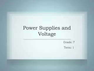
Chapter 4 Power Supplies and Voltage Regulators. 4.1 Half wave and full wave rectifiers. i = I m sin wt if 0 wt i = 0 if wt 2 where I m = V m / (R f + R L ). Half Wave Rectifier Parameters. I dc = 1 / 2 I dwt = 1 / 2 I m sinwt dwt = I m /

E N D
4.1 Half wave and full wave rectifiers • i = Im sin wt if 0 wt • i = 0 if wt 2 • where Im = Vm / (Rf + RL)
Half Wave Rectifier Parameters • Idc = 1 / 2I dwt = 1 / 2 Im sinwt dwt = Im / • Vdc = Idc RL = ImRL / • Irms = 1 / 2 i2 dwt = 1/ 2 Im2 sin2wt dwt = Im / 2 • Vrms = Vm / 2 • PIV = Vm • r = Vrms2 / Vdc2 –1 = 1.21 • = 0.405 /(1+rd/R)
Piecewise-linear diode model • V0 = 0, VS < VD0 • V0 = VS[R / (R + rD)] - VD0[R / (R + rD)], VS VD0
Full Wave Rectifier Parameters • Idc = 2 Im / • Vdc = 2 Im RL / • Irms = Im / 2 • PIV = 2 Vm • r = 0.48 • = 0.81 /(1+rD /R)
Bridge Rectifier • The bridge circuit is thus suitable for high-voltage applications. • PIV = Vmax
4.2 Capacitor filter • The pulsating nature of the output voltage produced by the rectifier circuits make them unsuitable as a dc supply for electronic circuits. A simple way to reduce the variation of the output voltage is to place a capacitor across the load resistor.
Capacitive Filter with Load • Vr = Vp / 2fCR
Example • Consider a peak rectifier fed by a 60 Hz sinusoid having a peak valued Vp = 100 V. Let the load resistance R = 10 K. Find the value of the capacitance C that will result in a peak-to-peak ripple of 2V. • Solution • Consider the circuit is a half-wave rectifier, then the value of capacitor is given by • C = Vp / VrfR • = 100 /(2 x 60 x 10 x103) = 83.3 F
4.3 Zener diodes, bandgap voltage references, constant current diodes • Zener Diodes
Bandgap (VBE) Reference • It is a “clever” circuit that generates a voltage with a positive temperature coefficient which is same as VBE's negative coefficient, so that when added to a VBE, the resultant voltage has zero temperature coefficient. • The bandgap reference can generate references having a temperature coefficient on the order of 10 ppm / C over the temperature range of 0C to 70C.
Bandgap (VBE) Reference • A voltage VBE is generated from a pn-junction diode having a temperature coefficient of approximately -2.2 mV / C at room temperature. Also generated is a thermal voltage Vt (Vt = KT/q) that has a temperature coefficient of +0.085 mV/C at room temperature. If the Vt voltage is multiplied by a constant k and summed with VBE voltage, then the output voltage is given as • Vref = VBE + kVt………………………….(1)
Practical Circuit • The input offset voltage of the otherwise ideal op-amp (VOS) has been included in the circuit. Transistors Q1 and Q2 are assumed to have emitter-base areas of AE1 and AE2, respectively.
If we assume for the present that VOS is zero, then the voltage across R1 is given as • VR1 = VBE2 - VBE1 = Vt ln (J2 / JS2) - Vt ln (J1 / JS1) • = Vt ln [(I2 AE1) / (I1AE2)] • where, • JS1,2 = collector current density (A/m2) • However the op-amp also forces the relationship • I1R2 = I2R3 • Hence, Vref = VBE2 + (R2 / R1) Vt ln [(R2AE1) / (R3AE2)] -------------------(2) • Comparing equation (2) with equation (1) we have • k = (R2 / R1) [(R2AE1) / (R3AE2)] • Thus k is defined in terms of resistor and emitter base area ratios.
A Practical Circuit • The Art of Electronics, p 335
IC Bandgap References • LM 285 – 1.2 operating voltage 1.235 V 1% • LM 285 – 2.5 2.50 V, using internal circuitry • These IC regulators are usable down to 10 A, i.e. much less than you can run any zener at, making these references excellent for micro-power equipment. • Max temp coeff. (Typical dyn. Impedance at 100 A • Best grade of LM 385 30 ppm / C (1k • 1N4370 800 ppm / C (3k • zener voltage is about 1.1 V only !! • when you need a precision stable voltage reference, these excellent bandgap Ics put conventional zener diodes to shame.
Constant Current Diode • JFET is chosen because it needs no gate bias • Current will be reasonably constant for VDS larger than a couple of volts • Current is unpredictable (because of IDSS spread) : 2N5484 ( a typical n-channel JFET) Has a specified IDSS of 1mA to 5 mA • Current regulator diodes are commercially available with gate tied to source, sorted according to current
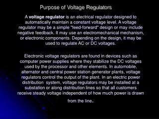
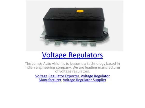
4.4 Voltage Regulators Most electronic devices require dc voltage to operate. Batteries are useful in low-power or portable devices, but operating time is limited unless the batteries are recharged or replaced. • The most economical power supply is some type of rectifier circuit. Unfortunately, some ac ripple voltage rides on the dc voltage, so the rectifier circuit does not deliver pure dc. An equally undesirable characteristic is a reduction in dc voltage as more load current is drawn from the supply. Since dc voltage is not regulated (that is, constant with changing load current), this type of power supply is classified as unregulated.
Example • Calculate output resistance Ro from the no-load and full-load measurements given as • ILNL = 0 ; VdcNL = 34 V; VdcFL = 24 V; ILFL = 1 A. Also predict dc output voltage at half-load where IL = 0.5 A. • Solution • Ro = (VdcNL – VdcFL) / ILFL = (34 – 24) / 1 = 10 ohm • For IL = 0.5 A, • Vdc = VdcNL – ILRo = 34 – (0.5)(10) = 29 V
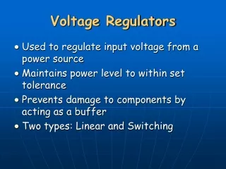
Regulated Power Supplies • An ideal regulated power supply is an electronic circuit designed to provide a predetermined dc voltage V0 which is independent of current Il drawn from Vo of the temperature, and also of any variation in the ac line voltage. • There are three reasons why an unregulated power supply is not good enough for many applications. The first is its poor regulation; the output voltage is not constant as the load varies. The second is that the dc output voltage varies with the ac input. The third reason is that the dc output voltage varies with the temperature, particularly because semiconductor devices are used. The circuit used to overcome the above three shortcomings and which reduce the ripple voltage is known as the voltage regulator.
Since the output dc voltage V0 depends on the input unregulated dc voltage VI, load current IL, and temperature T, then the change V0 in output voltage of a power supply can be expressed as follows: • V0 = (Vo / Vi )V0 + (Vo / IL ) IL + (Vo / T ) T • Or, Vo = SVVI + RoIL + STT • Where the three coefficients are defined as • Input regulation factor, SV = (Vo / VI) with IL = 0 and T = 0 • Output resistance, Ro = (Vo / IL) with VI = 0 and T=0 • Temperature coefficient ST = (Vo / T) with VI = 0 and IL = 0 • The smaller the value of the three coefficients, the better the regulation of power supply. The input voltage change VI may be due to a change in ac line voltage or may be ripple because of inadequate filtering.
Zener diode voltage regulator • Is = (Vin – Vz) / Rs • Under the no load condition, the zener current is equal to the Is. So while choosing the current limiting resistor Rs, the power rating of the zener diode should be considered. • (See example in course manual) • Zener diode voltage regulators are not used in most applications because • current is limited • Vz varies with Iz • Change in Vz due to temperature variation appears at the output
4.5 Series transistor zener diode voltage regulator • In this set up, the transistor (pass element) behaves like a variable resistor whose resistance is determined by the base current. The zener diode provides the voltage reference, and the base-to-emitter voltage of the transistor is the control voltage. The zener diode is reverse biased and that reverse current is furnished to it through resistor R. Although Vin is unregulated, it must remain sufficiently large, and R must be sufficiently small, to keep the zener in its reverse breakdown region. Thus, as the unregulated input voltage varies, Vz remains essentially constant.
Circuit Analysis • Keeping in mind the polarities of different voltages, we can apply KVL to get • VBE = Vz -V0 • Now we treat Vz as perfectly constant. Since above equation is valid at all times, any change in V0 must cause a change in VBE; in order to maintain equality. For example when current demand is increased by decreasing RL,V0 tends to decrease. It will increase VBE because Vz is fixed. This will increase forward bias of the transistor thereby increasing its level of conduction. This will lead to decrease in the collector-emitter resistance of the transistor which will slightly increase the input current to compensate or decrease in RL so that V0 = ILRL will remain at a constant value.
Findings • Advantages • Current is not limited by zener (load current is solely provided by the pass element) • Disadvantages • No provision for varying output voltage • Change in VBE and VR due to temperature variation appear at the output • Iz varies with VI, leading to variation in VR.
4.6 Series transistor, zener diode, constant current diode voltage regulator • Due to the use of constant current diode , the load current is essentially constant leading to more stable VR, thus more stable output voltage Vo is achievable.
The regulated power supply shown represents a case of voltage series feedback. If we assume that the voltage gain of the emitter follower Q1 (Q1 is also called the pass element) is approximately unity, then V0' V0 and • V0’ = Av Vin = Av (VR -V0) V0 • where = R2 / (R1 + R2) • V0 = VR Av / (1 + Av) • The output voltage Vo can be changed by varying the feedback factor . The emitter follower Q1 is used to provide current gain, because the current delivered by the amplifier Av usually is not sufficient. The dc collector voltage required by the error amplifier Av is obtained from the unregulated voltage.
Circuit Analysis • In the figure, Q2 is the comparison amplifier and the VR is the reference voltage. Here a fraction of the output voltage V0 is compared with the reference voltage VR. The difference V0 - VR is amplified by Q2. If the input voltage increases by Vi (say, because the power-line voltage increases), then V0 need increase only slightly, and yet Q2 may cause a large current change in R3. Thus it is possible for almost all of Vi to appear across R3 (and since the base-to-emitter voltage is small, also across Q1) and for V0 to remain essentially constant.
V0 = VR + VBE2 + R1 / (R1 + R2) V0 • or, V0 [1 – R1 / (R1 + R2 )] = (VR + VBE2 ) • or, V0 = (VR + VBE2 )(1 + R1 / R2) • or, V0 = (VR + VBE2) / • Hence a convenient method for changing the output is to adjust the ratio R1 / R2 by means of a resistance divider as shown in figure. • Also, Vo / T = (VR / T + VBE2 / T) (1 + R1 / R2) • Cancellation of temperature coefficient between reference diode and transistor Q2 can result in a very low Vo / T. • Example • Design a series regulator power supply to provide a nominal output voltage of 25 V and supply load current IL 1A. The unregulated power supply has the following specifications: • Vi = 50 5 V and ro = 10
Practical considerations • The maximum dc load current of the power supply is restricted by the maximum allowable collector current of the series transistor. The difference between the output and input voltages of the regulator is applied across Q1, and thus the maximum allowable VCE for a given Q1 and specified output voltage determines the maximum input voltage to the regulator. The product of the load current and VCE is approximately equal to the power dissipated in the pass transistor. Consequently, the maximum allowable power dissipated in the series transistor further limits the combination of load current and input voltage of the regulator
Protection • A power supply must be protected further from the possibility of damage through overload. In simple circuits protection is provided by using a fusible element. • Diodes D1 & D2 are non- conducting until the voltage drop across the sensing resistor RS exceeds their forward threshold voltage, Vr. Thus in the case of short circuit, the current Is would increase only up to a limiting point determined by • IS = (Vr1 + Vr2 – VBE1) / RS
4.8 IC voltage regulators • Three terminal voltage regulators • Three-terminal voltage regulators are voltage regulators in which the output voltage is set at some predetermined value. They therefore do not require any external feedback connections. As a result, only three terminals are required for this type of regulator: input (Vin), output (Vout) and a ground terminal. Since these regulators operate at a preset output voltage, the current limit resistor is also internal to the regulator. • The principal advantage of three terminal regulation is the simplicity of connection to the external circuit, with a minimum of external components required. • Although the three-terminal regulator offers only fixed output voltages, there are a wide variety of voltages available, both positive and negative.
78xx series • The voltage is specified by the last two digits of the part number and can be any of the following: 05, 06, 08, 10, 12, 15, 18 or 24. • 78xx is a low power version with built in circuitry for protection against over heating and excessive load current. • 79xx series • These are the negative regulators that work with negative input. The capacitor across the output improves transient response and keeps the impedance low at high frequencies. • LP2950 • These series of regulators draw only 75A of quiescent current and can regulate with as low as 0.4 V dropout voltage. • LT1085/4/3 • +5 and +12 available in each type with 3A, 5A and 7.5A respectively.
Adjustable 3 terminal regulator • LM 317 is a good example of an adjustable three terminal voltage regulator. It has no ground terminal, instead it adjusts Vout to maintain a constant 1.25 volts (bandgap) from the output terminal to the adjustment terminal. • In plastic or metal power package, it can deliver up to 1.5 A, with proper heat sinking. Vout = 1.25 (1 + R2 / R1) volts Higher current ratings: LM350 (3A), LM338 (5A), LM396(10A) Higher voltage ratings: LM317H (60V), TL 783 (125V)
Switching Mode Power Supply • Linear pass type power supply unit: • Large & heavy step down transformer is required to convert 115 (230) V ac to low voltage ac required for rectifiers. • Excess voltage is dissipated as heat in the pass transistor. • Instead of wasting the unused power, the switching regulator switches only the power needed to the output. Basically, the switching supply is a voltage-controlled switch.
The primary power is rectified and filtered as high voltage dc. It is then switched to high rate of speed, approximately 20-40KHz, and fed to the step-down transformer. This step-down transformer is only a fraction of the size of 50Hz unit, thus relieving the size and weight problem. The secondary side of the transformer is rectified and filtered to obtain the output. A sample of this output is sent back to the switch to control the output voltage. • Most switching power supplies regulate their output using a method called pulse width modulation. The power switch, which feeds the primary side of the transformer, is driven by a pulse width modulated oscillator. When output dc-level starts decreasing, more power is passed through the transformer, and similarly when the output dc level starts increasing, less power is passed to maintain the dc level constant.