Download
1 / 13
130 likes | 157 Vues
This system detects new signals efficiently using a heterogeneous computing platform with FPGA advancements and partitioning strategies for detection processing. Explore frequency division and time domain broadcast techniques.

E N D
Partitioning of a Signal Detection Algorithm to a Heterogeneous Multicomputing Platform Michael Vinskus Mercury Computer Systems, Inc. High Performance Embedded Computing (HPEC) Conference September 23, 2003
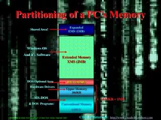
System Description • The goal of the acquisition system is to detect the presence of new signals in the environment in a timely manner so that they may be identified and exploited • A homogeneous system based on general purpose processors can be used to solve the problem, but advances in FPGAs allow for a higher processing density, especially in the channelizer • Current FPGAs can offer over a 10x computational density improvement over general purpose processors for certain applications. Unfortunately, most communication fabrics have not scaled at the same rate How can the I/O issue be managed? By partitioning across multiple processing elements! • Typical acquisition systems place the delay memory after the analog to digital converter. For demodulation, a digital down converter(DDC) is used to heterodyne and filter the delayed data stream • When the number of signals to demodulate becomes very large (>100), the typical DDC-based approach becomes cumbersome. FFT processing can allow the simultaneous down conversion and filtering of thousands of signals. The downside is an increase in the amount of memory needed to give the same time delay
The Channelizer • The channelizer decomposes the input sample stream into frequency channels by performing overlapped and windowed, short time Fourier transforms on the input data stream • Parameters: • 16384 point real DFT • 4:1 overlap and windowing (P = 4) • 16384 input sample maximum latency requirement • Output 8192 bins, complex, 24 bits per component (1200 MB/s) • The channelizer throughput is greater than most interconnect fabrics can support • Need to partition the problem
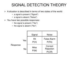
Detection Processing • The new energy alarm detects the presence of “new” signals and performs some rudimentary external measurements • High-input bandwidth and computational requirements necessitate partitioning • Partitioning strategies • Commutation • Time domain broadcast • Frequency division
Commutator Partitioning • Each processing partition generates the entire frequency sweep for a range of time slices • In this case, the channelizer is split into four partitions • Each partition processes a contiguous segment of the input data stream • By partitioning the problem in this manner, extra overhead to handle the segment boundaries is incurred • Also, the system latency increases due to time expansion nature of the commutation process • In this example, P-1 old input data blocks need to be received and P-1 blocks need to be sent • Total I/O overhead is 2(P-1) blocks for transfers greater than 2P-1 blocks of data
Commutator Implementation • To meet the one block latency requirement, only 1/4 of a block of new data is passed to each partition; 3/4 of the data comes from the other partitions. This results in the same data block being transferred an extra 3 times! • For this example, the input bandwidth increases from 200 MB/s to 800 MB/s. We’re going the wrong way!
Time Domain Broadcast • Each partition receives the entire data stream • No extra I/O overhead is incurred • Partitioning does not add latency • No communication between channelizer partitions • Still need to send all of the channelizer output data to the detector processors • If there are a sufficient number of detector processing elements allocated and they are located correctly in the fabric, then I/O bottlenecks can be avoided
Broadcast Implementation • Each fabric connection is a 266 MB/s half duplex link to the crossbar. Typical performance is around 250 MB/s • To accommodate the channelizer output rate, the output stream must be split across multiple connections • This complicates the data flow and fully utilizes the fabric I/O capacity in many places
Frequency Division Partitioning • Each node generates a subset of the frequency bins for all time slices • Each partition needs all of the time series data for each sweep • Able to pipeline the channelizer and detection processing with minimal inter-processor communication
Frequency Division Mapping • Each partition performs the front part of the FFT computations. This is inefficient, but the I/O issues are simpler • Uniform communication between partitions at partition boundaries only • Single element communication between channelizer partitions • Similar communication between detector partitions! • So why the unusual allocation of the frequency bins?
The algorithm exploits the efficient computation of the DFT of a 2N-point, real-valued, input sequence with an N-point complex transform Since the input data is real, only one half of the output spectrum needs to be computed for k = 0, 1, ..., N – 1. Frequency Division Rationale By processing a range of X(k), X(N-k) frequency pairs, twice as many output points can be calculated with only two extra additions!
Frequency Division Approach • Redundant computations are performed in each channelizer partition to reduce the system I/O requirements • Unlike the time partitioning case, most of the I/O movement occurs locally in the fabric Exchanges processing capacity for reduced I/O complexity
Multi-Antenna Implications • Adds an extra data dimension to the problem • Typical antenna arrays consist of 4 - 8 antenna elements • The detection algorithms are different than the single antenna case. Typically, eigenspace methods are employed • The channelizer is similar between the single and multi-antenna cases • Detection processing requires the time series data for each frequency bin • Log magnitude computation is not required • Eigenvalues and eigenvectors are computed for each bin, across all antennas • As shown in the previous example, frequency domain partitioning has advantages when I/O bound conditions occur • The majority of the data movement is local • High-speed local interconnects may be used instead of the fabric connections