Download

1 / 21
340 likes | 519 Vues
Inertial navigation. Basic principle. If we can measure the acceleration of a aircraft we can integrate the acceleration to get velocity integrate the velocity to get position deviation. X B = X A +dX Y B = Y A +dY Z B = Z A +dZ. Z. A(X A ,Y A ,Z A ). dX. dY. dZ. B(X B ,Y B ,Z B ).

E N D
Basic principle If we can measure the acceleration of a aircraft we can • integrate the acceleration to get velocity • integrate the velocity to get position deviation
XB=XA+dX YB=YA+dY ZB=ZA+dZ Z A(XA,YA,ZA) dX dY dZ B(XB,YB,ZB) X Y
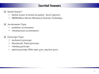
two options of INS • gimbaled or stabilized platform techniques • Strapdown techniques
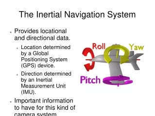
Gimbaled INS • A gimbal is a rigid with rotation bearings for isolating the inside of the frame from external rotations about the bearing axes. At least three gimbals are required to isolate a subsystem from host vehicle rotations about three axes, typically labeled roll, pitch, and yawaxes. • •The gimbals in an INS are mounted inside one another. Gimbals and torque servos are used to null out the rotation of stable platform on which the inertial sensors are mounted.
Strapdown inertial navigation concept • Accelerometers mounted directly to airframe (strapdown) and measure “body” acceleration • Horizontal/vertical accelerations computed analytically using direction cosine matrix relating body coordinated and local level navigation coordinates
Sensors fastened directly on the vehicle Strapdown INS
direction cosine matrix • Rotation about reference z axis through angle • Rotation about new y axis through angle • Rotation about new z axis through angle
effect of gravity • The main problem for an INS is to separate the vehicle acceleration from the effect of gravity on the accelerometers • In the stable platform, this is done by maintaining the accelerometers perpedicular to the gravity vector which allows us to ignore the effect of gravity • Another approach is to keep track of the gravity vector and subtract its effect from the outputs of the accelerometers
If the roll and pitch angles are Φ and Θ respectively • aX= gsin Θ • aY= gsinΦcos Θ • aZ= gcosΦcosΘ Therefore: Θ=sin-1(aX/g) and Φ= sin-1(aY/gcosΘ)