Download
1 / 31
310 likes | 313 Vues
1 - Routing Concepts. Rick Graziani Cabrillo College graziani@cabrillo.edu. Layer 3 Forwarding Concepts and Routing Principles. Rick Graziani Cabrillo College graziani@cabrillo.edu. Dest MAC. Src MAC. Source 192.168.1.10. Destination 192.168.3.22. FCS. 192.168.1.10/24.

E N D
1 - Routing Concepts Rick Graziani Cabrillo College graziani@cabrillo.edu
Layer 3 Forwarding Concepts and Routing Principles Rick Graziani Cabrillo College graziani@cabrillo.edu
Dest MAC Src MAC Source 192.168.1.10 Destination 192.168.3.22 FCS 192.168.1.10/24 192.168.3.22/24 192.168.2.0/24 192.168.1.0/24 192.168.3.0/24 How does a packet get forwarded from source to destination?
Each routing entry has a prefix (network address) and prefix length (subnet mask) • The prefix length indicates the minimum number of left-most bits that need to match the destination IP address for the entry to be considered a match. • The routing entry with the longest match (the entry with the longest prefix length) is used. • Default route (/0) is a 0 bit match and is used as the gateway of last resort. Dest MAC Src MAC Source 192.168.1.10 Destination 192.168.3.22 FCS 192.168.1.10/24 192.168.3.22/24 192.168.2.0/24 192.168.1.0/24 192.168.3.0/24 C 192.168.1.0/24 is directly connected, FastEthernet0/0 C 192.168.2.0/24 is directly connected, Serial0/0/0 S 192.168.3.0/24 [1/0] via 192.168.2.2 1. Examines its destination IP address 2. Searches the IP routing table with it's list of network addresses (prefixes) for the longest match
Source 192.168.1.10 Destination 192.168.3.22 192.168.1.10/24 192.168.3.22/24 192.168.2.0/24 192.168.1.0/24 192.168.3.0/24 C 192.168.1.0/24 is directly connected, FastEthernet0/0 C 192.168.2.0/24 is directly connected, Serial0/0/0 S 192.168.3.0/24 [1/0] via 192.168.2.2 3. Determine the routing entry's egress interface to be used to forward the packet • If the routing entry only has an next-hop IP address, a recursive lookup may be required if CEF (Cisco Express Forwarding) or similar technique is not used.
Data Link Header Source 192.168.1.10 Destination 192.168.3.22 Data Link Trailer 192.168.1.10/24 192.168.3.22/24 192.168.2.0/24 192.168.1.0/24 192.168.3.0/24 C 192.168.1.0/24 is directly connected, FastEthernet0/0 C 192.168.2.0/24 is directly connected, Serial0/0/0 S 192.168.3.0/24 [1/0] via 192.168.2.2 4. Encapsulates the IP packet into the data link frame of the outgoing or exit interface
Dest Add Src Add Source 192.168.1.10 Destination 192.168.3.22 FCS 192.168.1.10/24 ARP Cache IPv4MAC 192.168.2.2 ? 192.168.3.22/24 192.168.2.0/24 192.168.1.0/24 192.168.3.0/24 192.168.2.2 C 192.168.1.0/24 is directly connected, FastEthernet0/0 C 192.168.2.0/24 is directly connected, FastEthernet0/1 S 192.168.3.0/24 [1/0] via 192.168.2.2 4. Encapsulates the IP packet into the data link frame of the outgoing or exit interface • If the exit interface is a multaccess network such as Ethernet, the router will need to determine the destination MAC address for the next-hop IP address (or destination IP address). • Check ARP cache and if necessary send an ARP Request
Dest Add Src Add Source 192.168.1.10 Destination 192.168.3.22 FCS 192.168.1.10/24 192.168.3.22/24 192.168.2.0/24 192.168.1.0/24 192.168.3.0/24 C 192.168.1.0/24 is directly connected, FastEthernet0/0 C 192.168.2.0/24 is directly connected, Serial0/0/0 S 192.168.3.0/24 [1/0] via 192.168.2.2 5. The packet is then forwarded toward its destination. • May be the next-hop router or the final destination of the packet.
Control Plane Process Switching IP Routing Table Egress Interface Ingress Interface Data Plane 1st Packet 2nd Packet 3rd Packet 4th Packet 5th Packet CPU Analogy: Process switching solves a problem by doing math long hand, even if it is the identical problem. • Earliest switching method. • This is an older packet forwarding mechanism. • When a packet arrives on an interface, it is forwarded to the control plane where the CPU examines the routing table, determines the exit interface and forwards the packet. • It does this for every packet, even if the destination is the same for a stream of packets.
Control Plane Fast Switching IP Routing Table 1st Packet 2nd Packet 3rd Packet 4th Packet 5th Packet Egress Interface Ingress Interface Data Plane Fast Forward Cache CPU Analogy: Fast switching solves a problem by doing math long hand one time and remembering the answer for subsequent identical problems. • As routers had to process more packets, it was determined process switching was not fast enough. • Next evolution in packet switching was Fast Switching. • The first packet is process-switched (CPU + routing table) but it also uses a fast-switching cache to store next-hop information of the flow. • The next packets in the flow are forwarded using the cache and without CPU intervention.
Control Plane CEF Switching Egress Interface Ingress Interface Data Plane 1st Packet 2nd Packet 3rd Packet 4th Packet 5th Packet FIB and Adjacency Table CPU Analogy: CEF solves every possible problem ahead of time in a spreadsheet. • Preferred and default Cisco IOS packet-forwarding mechanism • CEF copies the routing table to the Forwarding Information Base (FIB) • CEF creates an adjacency table which contains all the layer 2 information a router would have to consider when forwarding a packet such as Ethernet destination MAC address. • The adjacency table is created from the ARP table.
Alex Zinin’s Routing Table Principles I know about my remote networks but it is not my responsibility if R2 and R3 know about their remote networks. • Principle 1: Every router makes its decision alone, based on the information it has in its own routing table.
Alex Zinin’s Routing Table Principles Just because I know how to get to R3’s LAN, 192.168.2.0/24 and I send that packet to R2, doesn’t mean R2 knows how to get there. ??? • Principle 2: The fact that one router has certain information in its routing table does not mean that other routers have the same information.
Alex Zinin’s Routing Table Principles And if the packet for R3’s LAN reaches 192.168.2.0/24, I don’t know if R3 has a route back to 172.16.3.0/24 for any return traffic. ??? • Principle 3: Routing information about a path from one network to another does not provide routing information about the reverse, or return, path.
Layer 3 Forwarding Concepts and Routing Principles Rick Graziani Cabrillo College graziani@cabrillo.edu
Populating an IP Routing Table, Administrative Distance, and Load Balancing Rick Graziani Cabrillo College graziani@cabrillo.edu
IP Routing tables are populated by: • Directly connected networks • At least one directly connected network is required • When an IP prefix/prefix length are configured on the router, similar to an end-device • Remote networks: • Static Routes: Manually configured • Dynamic routing protocol: Learned automatically
Topology: IPv4 and IPv6 :1 :2
Configuring Directly Connected Networks R1(config)# interface gigabitethernet 0/0 R1(config-if)# description Link to LAN 1 R1(config-if)# ip address 192.168.10.1255.255.255.0 R1(config-if)# ipv6 address 2001:db8:acad:1::1/64 R1(config-if)# ipv6 address fe80::1 link-local R1(config-if)# no shutdown R1(config-if)# exit R1(config)#
R1(config)# interface gigabitethernet 0/1 R1(config-if)# description Link to LAN 2 R1(config-if)# ip address 192.168.11.1255.255.255.0 R1(config-if)# ipv6 address 2001:db8:acad:2::1/64 R1(config-if)# ipv6 address fe80::1link-local R1(config-if)# no shutdown R1(config-if)# exit R1(config)#
R1(config)# interface serial 0/0/0 R1(config-if)# description Link to R2 R1(config-if)# ip address 209.165.200.225 255.255.255.252 R1(config-if)# ipv6 address 2001:db8:acad:3::1/64 R1(config-if)# ipv6 address fe80::1link-local R1(config-if)# clockrate 128000 ! Lab only R1(config-if)# no shutdown R1(config-if)# exit *Jan 30 23:01:17.323: %LINK-3-UPDOWN: Interface Serial0/0/0, changed state to down ! Will be down until other side has been configured
R1# show ip route Codes: L - local, C - connected, S - static, R - RIP, M - mobile, B - BGP <output omitted. Gateway of last resort is not set 192.168.10.0/24 is variably subnetted, 2 subnets, 2 masks C 192.168.10.0/24 is directly connected, GigabitEthernet0/0 L 192.168.10.1/32 is directly connected, GigabitEthernet0/0 192.168.11.0/24 is variably subnetted, 2 subnets, 2 masks C 192.168.11.0/24 is directly connected, GigabitEthernet0/1 L 192.168.11.1/32 is directly connected, GigabitEthernet0/1 209.165.200.0/24 is variably subnetted, 2 subnets, 2 masks C 209.165.200.224/30 is directly connected, Serial0/0/0 L 209.165.200.225/32 is directly connected, Serial0/0/0 R1# Network Address Interface Address Network Address Interface Address Network Address Interface Address
R1# show ipv6 route IPv6 Routing Table - default - 7 entries Codes: C - Connected, L - Local, S - Static, U - Per-user Static <output omitted> C 2001:DB8:ACAD:1::/64 [0/0] via GigabitEthernet0/0, directly connected L 2001:DB8:ACAD:1::1/128 [0/0] via GigabitEthernet0/0, receive C 2001:DB8:ACAD:2::/64 [0/0] via GigabitEthernet0/1, directly connected L 2001:DB8:ACAD:2::1/128 [0/0] via GigabitEthernet0/1, receive C 2001:DB8:ACAD:3::/64 [0/0] via Serial0/0/0, directly connected L 2001:DB8:ACAD:3::1/128 [0/0] via Serial0/0/0, receive L FF00::/8 [0/0] via Null0, receive R1# :1 :2 Network Address Interface Address
Example of Configuring a Static Route Assuming other routers have been configured R1(config)# ip route 10.1.1.0 255.255.255.0 209.165.200.226 R1(config)# ipv6 route 2001:db8:acad:4::/64 2001:db8:acad:3::2 R1# show ip route <partial output> S 10.1.1.0 [1/0] via 209.165.200.226 R3#show ipv6 route S 2001:DB8:ACAD:4::/64 [1/0] via 2001:DB8:ACAD:3::2
Example of Configuring Dynamic Routing Assuming other routers have been configured R1(config)# router ospf 1 R1(config-router)# network 192.168.10.0 0.0.0.255 area 0 R1(config-router)# network 192.168.11.0 0.0.0.255 area 0 R1(config-router)# network 209.165.200.224 0.0.0.3 area 0 R1(config-router)# end R1# show ip route O10.1.1.0/24 [110/648] via 209.165.200.226, 00:06:03, Serial0/0/0 O 10.1.2.0/24 [110/648] via 209.165.200.226, 00:06:03, Serial0/0/0
Administrative Distance Only a directly connected route can have an AD of 0 • Administrative Distance (AD) is used when the router has multiple sources (connected, static, dynamic) for a route with the same prefix/prefix length. • Cisco AD represents the “trustworthiness” of the route source - the lower the AD, the more trustworthy the source of the route • If multiple paths to a destination are offered to the routing table, the path with the lowest AD is installed.
R1(config)# router ospf 1 R1(config-router)# network 192.168.10.0 0.0.0.255 area 0 R1(config-router)# network 192.168.11.0 0.0.0.255 area 0 R1(config-router)# network 209.165.200.224 0.0.0.3 area 0 R1(config-router)# end R1# show ip route O10.1.1.0/24 [110/648] via 209.165.200.226, 00:06:03, Serial0/0/0 O 10.1.2.0/24 [110/648] via 209.165.200.226, 00:06:03, Serial0/0/0 R1# config t R1(config)# ip route 10.1.1.0 255.255.255.0 209.165.200.226 R1# show ip route <partial output> S 10.1.1.0/24 [1/0] via209.165.200.226 O10.1.2.0/24 [110/648] via 209.165.200.226, 00:06:03, Serial0/0/0
Best Path Which path is my “best path”? ? • Router’s determine best-path to a network: • Depends on the routing protocol • A protocol used to between routers to determine“best path” • Routing protocols use their own rules and metrics. • A metric: • Quantitative value used to measure the distance to a given route. • Best path: • Path with the lowest metric.
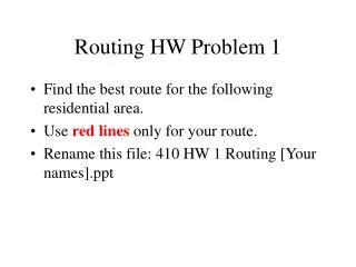
To reach the 192.168.1.0/24 network it is 2 hops via R2 and 2 hops via R4. Load Balancing ? ? 192.168.1.0/24 What happens if a routing table has two or more paths with the same metric to the same destination network? (equal-cost metric) Router will perform equal-cost load balancing. All routing protocols (RIP, EIGRP, OSPF) support equal cost load balancing; EIGRP also supports unequal cost load balancing.
R1# show ip route static <partial output S 10.1.1.0/24 [1/0] via 209.165.200.226 R1# show ip route ospf <partial output> O 10.1.2.0/24 [110/648] via 209.165.200.226, 00:06:03, Serial0/0/0 Routing Source Remote network AD Route Metric IPv4 address of next-hop router Egress (Exit) Interface
Populating an IP Routing Table, Administrative Distance, and Load Balancing Rick Graziani Cabrillo College graziani@cabrillo.edu