Download

1 / 64
640 likes | 842 Vues
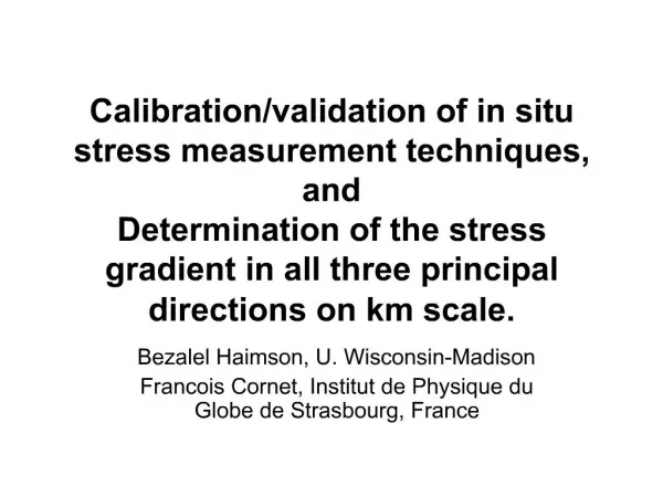
Bad Reconstruction. Full Spectrum. Distance (cms). c 2 Approach. Calibration Curve. Counts. Proposed Solution to HPBCR. Photo Peak. Compton. 0.89 Mev. 1.12 Mev. Good Calibration Curve. Acquire Photopeak. Good Reconstruction. CARPT Calibration Issues . Poster 1. 1.0mm. 2.3mm.

E N D
Bad Reconstruction Full Spectrum Distance (cms) c2 Approach Calibration Curve Counts Proposed Solution to HPBCR Photo Peak Compton 0.89 Mev 1.12 Mev Good Calibration Curve Acquire Photopeak Good Reconstruction CARPT Calibration Issues Poster 1
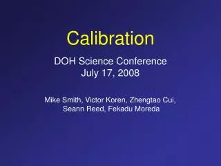
1.0mm 2.3mm 0.8mm N=100 rpm, QG=7.5 lit/min, Z=10.0 cms 250 mm 150 mm Poster 2 Gas Liquid Studies in Stirred Tank Reactor • New techniques in CT implementation result in better reconstruction!!! How ??? • Cross sectional gas holdup distributions (at different axial planes) in a Stirred Tank Reactor (for the first time!!) • Detailed local fluid dynamic information in gas-liquid flows in stirred tank (for first time!!)
Peter Spicka • research associate at CREL since 2001 • bubble columns, trickle beds • CT & CARPT experimental studies and CFD simulations CHEMICAL REACTION ENGINEERING LABORATORY Poster I: Review of CARPT/CT Experimental Database for Bubble Columns Operating in the Churn-Turbulent Regime Contributors: Jinwen Chen, Abdenour Kemoun, Sailesh Kumar, Shadi Saberi, Sujatha Degaleesan, Puneet Gupta, Booncheng Ong, Shantanu Roy, Qingi H. Wang Poster II:Effect of Nozzle Orientation of the Cross Sparger and Pressure on Bubble ColumnHydrodynamics
Review of CARPT/CT Experimental Database for Bubble Columns Operating in the Churn-Turbulent Regime • Different effects studied: • gas superficial velocity, liquid properties, pressure • column diameter, internals, gas distributor and solids concentration • DOE project (1995-2002) • Participants: Air Products, Ohio State University, Sandia National Laboratories and Washington University • Objectives: • effect of specific variables on observed flow patterns in bubble columns • engineering type models for flow and mixing in bubble columns • data for gas hold-up, velocity and turbulence profiles for validation of CFD codes • Scale up of bubble columns: • correlations for liquid centerline velocity, gas holdup, holdup and liquid velocity radial profiles and eddy diffusivities
Effect of Nozzle Orientation of the Cross Sparger and Pressure on Bubble ColumnHydrodynamics Nozzle orientation of the sparger • important design issue since it may affect the length of the flow development region (Schollenberger et al., 2000) • sparse information in the available literature Goals • to quantitatively determine the variation of gas hold-up, liquid recirculation and mixing due to variations in nozzle orientation and pressure • to compare the exp. data with 1-D recirculation model due to Kumar (1992) Gas holdup Liquid velocity profile • Experiment • 6” I.D. stainless steel column • cross-sparger, two nozzle orientations: facing upwardand downward • Air-water system • Pressure: 1 bar and 4 bars • UG= 5 cm/s (only CT) and 20 cm/s
Development of Improved Engineering Models for Flow, Mixing and Transport in Bubble Columns(Review of Phenomenological Model accomplished in CREL during 1995-2001) Tracer experiments during Methanol, Fischer-Tropsch and Dimethyl Ether Synthesis Gas tracer: Ar41 Liquid tracer: Powdered oxide of Mn56 (Mn2O3) suspended in the heat transfer oil Solid tracer: Catalyst particles doped with an oxide of Mn56
Contents • Suitability of the Axial Dispersion Model • One Dimensional Recirculation Model • One Dimensional Recycle with Cross Flow and Dispersion Model • Two-Dimensional Convection-Diffusion Model • Gas Phase Recirculation and Dispersion Model • Scale-up Strategy • Comparison of experimental and simulated tracer responses • What is the next step?
cross-section along with scintillation detectors and their lead shielding DME Synthesis Radioactive Tracer Studies in the AFDU Reactor during Dimethyl Ether (DME) Synthesis
Schematic of the reactor compartmentalization for the gas-liquid mixing model with interphase mass transfer (Gupta, 2001)
G • The engineering models needs input • Only Eulerian model seems feasible for churn turbulent flow regime • In churn turbulent regime, bubble size is widely distributed; the mean bubble diameter seems to be the simplest assumption • However, it is difficult to choose the “right” bubble diameter without going through tedious trial-and-error procedure • If one try to change to another column or operation condition, the “right” bubble diameter normally may not work any more L We need to predict rather than input bubble diameter, we had better predict it locally! G Implementation of Breakup and Coalescence Models into CFD of Bubble Column Flows ???
Gas Outlet Gas Inlet Bubbly flow regime CFD Modeling of Bubble Column Flows (Review of CFD activities in CREL 1995-2001) Gas Outlet • Contributors: • Dr. M. P. Dudukovic • Dr. M. H. Al-Dahhan • Dr. S. Kumar • Dr. Y. Pan • Dr. M. Rafique • Mr. P. Chen • Compiled by: M. Rafique • Research Associate • Ph.D. (Fluid Mechanics), INPL, France Acknowledgement: DOE Contract: DE FC 22 95 PC 95051 • Outline: • Hydrodynamics of bubble columns • Eulerian-Eulerian Two-Fluid Model • Algebraic Slip Mixture Model (ASMM) • Hydrodynamics of (passive) tracers (gas/liquid) in bubble column flows • Implementation of the Bubble Population Balance in CFD Gas Inlet Churn turbulent regime
D=15.2 cm D=15.2 cm width width L=10D =152 cm L=10D =152 cm 10 cm 10 cm Ug Ug =1cm/s =1cm/s 0.2 cm 0.2 cm 2D & 3D dynamic simulations 2D 3D Mesh system & Gas holdup contours
Numerical (liquid) Tracer Study Numerical particle tracking (calculation of turbulent diffusivities) 0 sec 2 sec 4 sec 6 sec 9 sec 19 sec
Meso-scale modeling of bubble column flows M. Rafique, M. H. Al-Dahhan, M. P. Dudukovic • Objective: • To simulate the bubble column hydrodynamics by resolving meso-scale flow structures through grid refinement. • To study the effect of attraction and repulsion forces on the hydrodynamics D=15.2 cm D=15.2 cm width Fine grid (0.2x0.25 cm) L =110 cm Coarse grid (0.5x0.5 cm) 10 cm 10 cm Ug Ug =1cm/s =1cm/s 0.2 cm
Instantaneous contours of gas volume fraction Coarse grid Cd+Cv Fine grid Cd+Cv Fine grid Cd+Cv+Catt
CHEMICAL REACTION ENGINEERING LABORATORY Measurement of Bubble Dynamics in Bubble Columns Using Four-point Optical Probe J. L. Xue, M. H. Al-Dahhan & M. P. Dudukovic In cooperation with Robert F. Mudde Delft University of Technology, The Netherlands Chemical Reaction Engineering Laboratory (CREL) Oct. 24, 2002 Optical Fiber Probes for Bubble Dynamics Measurement in Bubble Columns J. L. Xue, M. H. Al-Dahhan & M. P. Dudukovic In cooperation with Robert F. Mudde Delft University of Technology, The Netherlands Chemical Reaction Engineering Laboratory (CREL) November, 2001
CHEMICAL REACTION ENGINEERING LABORATORY Motivation • bubble dynamics, i.e. bubble size distribution, bubble velocity distribution, specific interfacial area and gas holdup are among the key parameters that affect the hydrodynamics in bubble columns. • Measurement of bubble dynamics is difficult, especially in churn-turbulent flows. • Non-invasive techniques, e.g. video imaging techniques, are limited to 2-D transparent columns. and can not be used in real 3-D systems which are opaque due to high volume fraction of the dispersed phase. • Optical probes can be applied in practical 3-D systems. The measurements of bubble dynamics by two-point probes are not reliable. Four-point optical probe was adopted in this research to measure the bubble dynamics in bubble columns.
CHEMICAL REACTION ENGINEERING LABORATORY The Configuration of the Four-point Optical Probe With a new data processing algorithm, it can measure: Bubble velocity vector Bubble size Specific interfacial area Gas holdup Side view Bottom view
CHEMICAL REACTION ENGINEERING LABORATORY Computed Tomography in Slurry Bubble Column Reactors Ashfaq Shaikh, M.H. Al-Dahhan Acknowledgements: DE-FG-26-99FT40594 CREL Annual Meeting October 24, 2002
CHEMICAL REACTION ENGINEERING LABORATORY • Evaluate the CT/Overall gas holdup algorithm System: Therminol LT-air-glass beads (150 m) Mimic fluid Single source CT Two-phase systems Three-phase systems One equation, two unknowns Need one more equation CT/Overall gas holdup (Rados, 2002) Sensitivity analysis Assumptions in CT/Overall gas holdup procedure has been critically examined
Assessing and Reinforcing the Phenomenological Consistency of Multiphase Flow Artificial Neural Network Correlations L.A. Tarca, B.P.A. Grandjean, F. Larachi Classically built ANN models may be phenomenological consistent in vicinity of some data points but not in the whole input space Large prediction errors mL Piché et al. (2001) [3] Counter-current packed bed
bm bm 1 1 N N 10 10 U U N N G G 13 13 N N 14 14 U U N N L L 18 18 … … N N 23 23 … … r r log log N N 26 26 G G N N 27 27 m m b b L L 1 1 bm bm N N a a 2 2 9 9 T T N N 10 10 b b D P / Z S S N N e e 2 2 log log ^10 ^10 13 13 N N r g 14 14 L … N N … f f 21 21 N N … … 24 24 N N Z Z b b 27 27 3 3 D D log log bm bm C C N N 3 3 10 10 r r N N L L 14 14 N N 17 17 s s N N L L , 18 18 … … N N m m 24 24 G G N N … … 27 27 Using phenomenological error (PCE) of the trained models we guide a Genetic Algorithm search for pertinent dimensionless numbers to predict a reactor characteristic Pressure drop in counter-current packed beds Phenomenological Consistency Error Phenomenological and prediction error decrease by combining multiple “good” ANNs
THEORY OF TRICKLE BED MAGNETOHYDRODYNAMICS IN INHOMOGENEOUS MAGNETIC FIELDS – Potential route to process intensification by I. Iliuta and F. Larachi • for positive magnetic gradients, gas magnetization force amplifies the effect of gravity (macro-gravity) and two-phase pressure drop is reduced When magnetic gradients are positive, liquid holdup increases with increasing |BdB/dz| because the driving force decreases G=1.2 kg/m3 G=47 kg/m3 When magnetic gradients are negative, liquid holdup decreases with increasing |BdB/dz| because the driving force (two-phase pressure drop) increases - for negative magnetic gradients, the upward gas magnetization force reduces the effect of gravity (sub or micro-gravity) and two-phase pressure drop increases
Elevated levels of magnetic field gradient improve the liquid holdup and thus the wetting efficiency of the catalyst particle Because phenol oxidation is liquid-reactant limited, as catalyst wetting improves the phenol conversion increases significantly
Prediction of HETP for randomly packed tower operation: Integration of aqueous and non-aqueous mass transfer characteristics into one consistent correlationSimon PICHÉ, Stéphane LÉVESQUE, Bernard GRANDJEAN,Faïçal LARACHIDepartment of chemical engineering & CERPICQuébec, CANADA G1K 7P4 G L S POLLUTION CONTROL:Particulate removal, SO2, NOX, VOC & TRS scrubbing WATER PURIFICATION:Ammonia stripping and recovery, VOC stripping DISTILLATION:Styrene purification (Ethylbenzene - Styrene separation) (Vacuum or Pressure)Demethanizers(ex: CH4 removal / heavy feedstock) G L OBJECTIVE: Build a new, efficient & consistent correlation using an artificial neural network, dimensionless analysis & data (HETP, KGaW, KLaW) reconciliation procedure that could predict either HETP for distillation or kGaW, kLaW, KGaW & KLaW for absorption and stripping DATABASE: 3770 absorption/stripping measurements 2357 distillation measurements
General procedure and Results (1) Testing of ANN correlations developed for aqueous solutions [1] on HETP (non-aqueous solutions) (2) Extraction of pseudo interfacial areas from HETP and mass transfer coefficients (with previously developed ANN-kg ) & development of new interfacial area correlation (ANN-aW) (3) Weights reconciliation on the 6 mass transfer parameters (HETP, aw, kLaw, kGaw, KLaw, KGaw) ANN-awI & ANN-kgI testing on HETP m = 76%, s = 100% ANN STRUCTURES:g = G (gas) and L (liquid) [1] aw/aT = f (ReL, FrL, EoL, wall factor, c) – ANN-awI kg /(aTDg) = f (Reg, Frg, Scg, c) – ANN-kgI This work aw/aT = f (ReL, FrL, EoL, wall factor, c,RSI) - ANN-awII kg /(aTDg) = f (Reg, Frg, Scg, c) – ANN-kgII RSI (Relative stability index) = (dsL/dxvol) / sL(mixture) RSI=0 (aqueous solutions); RSI<>0 (non-aqueous mixtures) STATISTICAL PERFORMANCE: HETP (N=2357, m=21%); aW/aT (N=325, m=24%); kLaW/kGaW (N=1461, m=23%); KLaW/KGaW (N=1984, m=29%) HETP, Kgaw & kgaw(exp) (5,802 data) kg(cal) ANN-kgI aw(pseudo) (5,802 data) ANN-aw(3) aw(exp) (325 data) ANN-aw(3) & ANN-kgI weights reconciliation HETP, KLaw, KGaw, kLaw, kGaw, aw (6,127 data) ANN-awII ANN-kgII [1] Piché, S., Larachi, F. & Grandjean, B., Reconciliation procedure for gas-liquid interfacial area and mass transfer coefficient in randomly packed towers, Ind. Eng. Chem. Res., 41 (19) (2002) 4911-4920.
CHEMICAL REACTION ENGINEERING LABORATORY Modelling of Radioactive Tracer Distribution in Bubble Columns by Chengyu Mao Advisor: Prof. M.P. Dudukovic Prof. P.A. Ramachandran
CHEMICAL REACTION ENGINEERING LABORATORY Many engineering models are available for description of flow, mixing, and transport in bubble columns. However, their accuracy to simulate and predict experimental data needs to be verified. • Liquid Recirculation Model • Recycle with Cross Flow and Dispersion Model (RCFDM) • Single Bubble Class Model (SBCM) • Distributed Bubble Size Model (DBSM) • Two Dimensional Convection with Eddy Diffusion Model
CHEMICAL REACTION ENGINEERING LABORATORY Single Bubble Class Model (SBCM) Two Dimensional Convection with Eddy Diffusion Model Liquid tracer concentration distribution Method 1 Calculate Cross-Sectional concentration, normalize and compare with data Method 3 Calculate 3D Response accounting fully for the attenuation of radiation, normalize and compare with data Method 2 Calculate 2D Response accounting approximately for the attenuation of radiation, normalize and compare with data
Liquid Maldistributionin Trickle Bed ReactorsExperimental and CFD Modeling Study Nicolas Dromard Master in Process Engineering, INPL, Nancy, FRANCE Chemical and Process Engineer, ENSIC, Nancy, FRANCE M.P. Dudukovic, M.H. Al-Dahhan, P. Spicka Chemical Reaction Engineering Laboratory, Washington University St Louis, USA D. Védrine, J. Bousquet Centre Européen de Recherche et Technique, TOTALFINAELF Harfleur, FRANCE
Liquid Maldistribution in TBRs • An Experimental Study • How to quantify maldistribution? • Determination of the parameters responsible for maldistribution • A step to CFD modeling • Generate a pseudo random porosity profile ?
input output Motivation C0, usL Scale up of packed bed: Simulation vs huge amount of experimental work ? How to choose multiple level model for reaction system of interest Xa, C, usL, Pellet scale Objective • Understand and compare the hierarchy of model for catalytic multiphase packed-bed reactors • Capture the time-dependent reaction features of catalytic wet oxidation in packed beds Completely actively wetted Half wetted Completely inactively wetted CHEMICAL REACTION ENGINEERING LABORATORY CREL Annual Meeting, 2002 Jing Guo Dr. M. H. Al-Dahhan Multiphase Packed-bed Reactor Modeling Reactor scale
C i, 0 Reactor Axis C i, 1 C i, 2 Reactor Scale Ul, Ug C i, j C i, N-1 C i, N El-Hisnawi Model CHEMICAL REACTION ENGINEERING LABORATORY Pellet scale Pellet scale Combination of Reactor and Pellet Scale Model Wet side Dry side Ci,j Beaudry Model Reaction wet oxidation of phenol over deactivating catalyst I:reactant component J:Cell sequence El-Hisnawi Model Predict axial concentration distribution Beaudry Model Active site distribution after 110 hours Refine local effectiveness factor Predict catalyst local performance
Poster 1 Plate 2 Plate 1 4" 4” Guide for the source New CT Setup and studies on Gas-Liquid Hold-up in Structured Packing using CT • Main difference between the old and new CT • Resolution Characteristics of new CT setup • Gas Liquid Flow Characteristics (hold-up and pressure drop) in a 12 inch Structured packing Shaibal Roy Muthanna Al-Dahhan
Poster 2 A Study of Structured Packing for Solid Catalyzed Gas-Liquid Reaction Shaibal Roy Muthanna Al-Dahhan Structured Packing for solid catalyzed gas-liquid reaction provides • Large Volumetric productivity • Lower pressure drop • Excellent mass transfer properties • Higher selectivity (low axial dispersion, short diffusion length scale) • Ease of scale-up Motivation
Research Objective The overall objective of the proposed study is to develop better understanding and fundamentally based model for comparison of structured packing (e.g. Monolith and other selected configuration) with conventional reactors for multiphase reactions Research Goal Hydrodynamic aspects in structured packing Apparent Kinetic model with extrudates And washcoated monolith Combined effects in overall performance of structured packing for multiphase reactions Compare with conventional packed bed reactor Develop model for performance prediction
A Non-Invasive Method for Overall Solids Flux Measurements in a Circulating Fluidized Bed (CFB) Satish Bhusarapu, Pascal Fongarland, M. H. Al-Dahhan and M. P. Dudukovic’ CREL Annual Meeting October 24, 2002 Chemical Reaction Engineering Laboratory Department of Chemical Engineering St.Louis, MO 63130
Challenge : How to measure overall solids mass flux accurately in a CFB ? Obtain solids velocity and concentration in a standpipe where solids hold up is high • Solids velocity – “time of flight” measurements – track a single radioactive tracer using a two detector set-up • Solids concentration – g-ray line densitometry Overall solids flux at varying operating conditions