Download
1 / 34
360 likes | 696 Vues
SYS 5100 - Modern Control Engineering - Winter 2007. Educational Model of Control System for Robot Arm. Team Members : Irena Karasik Sylvain Ganter Olivier Paultre Jeong Ja Kong

E N D
SYS 5100 - Modern Control Engineering - Winter 2007 Educational Model of Control System for Robot Arm Team Members : Irena Karasik Sylvain Ganter Olivier Paultre Jeong Ja Kong TA : Wei Yang Professor : Riadh Habash - April 4th, 2007 -
References [1] Kok Kiong Tan and Han Leong Goh, “Development of a Mobile Spreadsheet-Based PID Control Simulation System”, IEEE Transaction on Education, PP. 199-207, may 2006 [2] Guoguang Zhang and Junji Furusho, “Control of Robot Arms using Joint Torque Sensors”, IEEE Control Systems, pp.48-55, 1998 [3] Gloria Suh, Dae Sung Hyun, Jung Il Park, Ki Dong Lee, Suk Gyu Lee, “Design of a Pole Placement Controller for Reducing Oscillation and Settling Time in a Two-Inertia Motor System”, IECON’01:The 27th Annual Conference of the IEEE Industrial Electronics Society, pp.615-620, 2001 [4] Estico Rijanto, Antonio Moran and Minoru Hayase, “Experimental Positioning Control of Flexible Arm Using Two-Degrees-of-Freedom Controller”, p127 [5] Miomir K. Vukobratovic, Aleksandar D. Rodic, “Control of Manipulation Robots Interacting with Dynamic Environment: Implementation and Experiments”, IEEE Transactions on Industrial Electronics, Vol.42, No.4, August 1995 [6] Textbook : “Modern Control Theory”
References [1] Development of a Mobile Spreadsheet-Based PID Control Simulation System - To control the Temperature of Thermal Chamber - Mobile PID Tuning Preparatory Exercise - Mobile Spreadsheet Simulator
References [2] Control of Robot Arms using Joint Torque Sensors - Two-Inertia System Modeling - With Joint Torque Feedback - Dealt with Pole Assignment & Effect of Disturbance - ½ Bandwidth of resonance frequency (PD Controller) - Identical Damping Coefficients ( 1 = 2 ) - A wider bandwidth and better disturbance rejection over conventional PD control
References [3] Design of a Pole Placement Controller for Reducing Oscillation and Settling Time in a Two-Inertia Motor System - Identical Real Part settling time - Comparison among 3 controller I-P, I-PD, State Feedback control - Conventional ITAE & Weighted ITAE - Full state feedback control is the best in terms of oscillation & settling time
References [4] Experimental Positioning Control of Flexible Arm Using Two-Degrees-of-Freedom Controller Two Methods: * 2) is better 1) Feedback Control (frequency domain) Based on Model matching method using the inverse dynamics of the arm system 2) Feed-forward Control (time domain) Using the inverse dynamics of the non-minimum phase system of the arm
References [5] Control of Manipulation Robots Interacting with Dynamic Environment: Implementation and Experiments
Our Goals • To design a control system for Robot Arm, • To practice the control theories acquired in class, • To provide an educational model of control theories with Robot Arm model, • To help the students understand the control system theory and increase their interest in the subject matter.
Team & Roles Start Topic Selection • Irena Karasik (Model Analysis) • Sylvain Ganter (Controller Design) • Olivier Paultre (SIMULINK) • Jeong Ja Kong (Controller Design, Leader) Role Assignment References Search Weekly Meeting Plant Modeling Controllers Design MATLAB Simulation Educational Model End
Steps Step3 Step1 Actuator + Process (Robot Arm) Step2 Input (Reference) Output (Arm Dynamics) Controller GUI (Controller Gain Adjust) Step3 Step1 : Analysis of system characteristic (From the Dynamics of Robot Arm) Step2 : Controller Design (P, PI, PD, PID, Phase-Lead or -Lag Compensator) Step3 : Simulation (MATLAB)&User Interface Design (SIMULINK) Step4 : Evaluation of the performance of the Controlled system
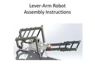
250 . s(s+2)(s+40)(s+45) G (s) = Dynamic Model of Robot Arm
Characteristics of Plant Model • State-space Model | -87 -1970 -3600 0 | | 1 | | | | | A = | 1 0 0 0 | B = | 0 | | | | | | 0 1 0 0 | | 0 | | | | | | 0 0 1 0 | | 0 | C = | 0 0 0 250 | D = | 0 |
Location of Poles & Zeros Characteristics of Plant Model
Characteristics of Plant Model • Steady state error (Type ) Step Input : ess= 0 Ramp Input : With unit ramp input, Kv = lim sG(s) = .0694 ess = A/Kv =14.4 Parabolic Input : ess =
Characteristics of Plant Model • Controllability & Observability det [Pc] = 3.9 10 9 Process is controllable det [Po] = 1 Process is observable
Characteristics of Plant Model • Time Response & Frequency Response Ts = P.O = Phase Margin = 87.8º
Settling Time, Ts 1.2 sec Maximum Overshoot, P.O 20% Phase Margin, PM 45° Design Criteria
Controller Design • Unity Feedback Control Ts = 80 sec P.O = 0 % PM = -180°
Controller Design • P Control Settling time is several times greater than the desired value Ts = 4.26 sec P.O = 20 % PM = 79.7 °
Controller Design • PI Control Settling time is still too large Ts = 4.25 sec P.O = 20 % PM = 77.3 °
Controller Design • PD Control Settling time is better, but still does not meet our criteria Ts = 1.43 sec P.O = 20 % PM = 96.7 °
Controller Design • PID Control Settling time is better, but still does not meet our criteria Ts = 1.75 sec P.O = 20 % PM = 69.1 °
Controller Design • Phase Lead Compensator Ts = .84 sec P.O = 20 % PM = 45 ° meets our design criteria
Controller Design • Phase Lead Compensator (Continued) Open loop (Loop Transfer function) Closed-loop
Closed-Loop Response Input Selection Controller Selection Output Scope Root-Locus Drawing Scope Selection Controllability & Observability Check Comparison Between Controllers Pole-zero & Others Bode Plot
Conclusion • It is not possible to meet the design criteria with P, PI, PD, & PID Controller of this Arm Model Controller Gain Change Effects on Both (Time, Overshoot)! The Best Controller for this model is Phase-Lead Compensator. Student can learn the Control theory easily: Parameter Change See the effect ! 2 Different Controllers Compare the effect !
Challenge • To Model the Robot-Arm System • To find out moreinteracting educational Model • To provide more Visual Learning • To add more controllers