Download
1 / 15
160 likes | 350 Vues
Analytical Vs Numerical Analysis in Solid Mechanics. Created by: Krishna Teja Gudapati. Dr. Arturo A. Fuentes. Solid Mechanics.

E N D
Analytical Vs Numerical Analysis in Solid Mechanics Created by: Krishna Teja Gudapati Dr. Arturo A. Fuentes
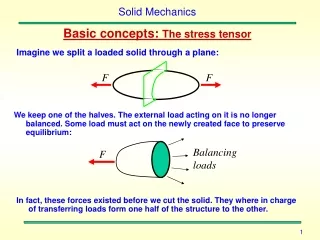
Solid Mechanics • Solid Mechanics is a collection of mathematical techniques and physical laws that can be used to predict the behavior of a solid material when subjected to loading. • Engineers and scientists use solid mechanics for a wide range of applications, including: Mechanical Engineering Geo-Mechanics Civil Engineering Manufacturing Engineering Biomechanics Materials Science Microelectronics Nanotechnology To know more about solid mechanics visit: http://www.engr.panam.edu/~afuentes/mechmat.htm
Defining a Problem in Solid Mechanics • Regardless of the field, the general steps in setting up a problem in solid mechanics are always the same: 1. Decide what you want to calculate 2. Identify the geometry of the solid to be modeled 3. Determine the loading applied to the solid 4. Decide what physics must be included in the model 5. Choose (and calibrate) a constitutive law that describes the behavior of the material 6. Choose a method of analysis 7. Solve the problem
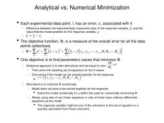
Choosing a Method of Analysis • Once you have set up the problem, you will need to solve the equations of motion (or equilibrium) for a continuum, together with the equations governing material behavior, to determine the stress and strain distributions in the solid. Several methods are available for this purpose. • Analytical solution (or) Exact solution: There is a good chance that you can find an exact solution for: 1. 2D (plane stress or plane strain) linear elastic solids, particularly under static loading. 2. 2D viscoelastic solids 3. 3D linear elasticitity, usually solved using transforms. 4. 2D (plane strain) deformation of rigid plastic solids (using slip line fields)
Choosing a Numerical Analysis Method • Numerical Solutions: are used for most engineering design calculation in practice. Numerical techniques include 1. The finite element method – This is the most widely used technique, and can be used to solve almost any problem in solid mechanics. 2. The boundary integral equation method (or boundary element method) – is a more efficient computer technique for linear elastic problems, but is less well suited to nonlinear materials or geometry. 3. Free volume methods – Used more in computational fluid dynamics than in solids, but good for problems involving very large deformations, where the solid flows much like a fluid. 4. Atomistic methods – used in nanotechnology applications to model material behavior at the atomic scale. Molecular Dynamic techniques integrate the equations of motion (Newton’s laws) for individual atoms; Molecular static's solve equilibrium equations to calculate atom positions.
Complex Bio-Mechanical Example Let us consider a human leg bone (Femur) with the following mechanical properties that are taken from an average healthy human being • Mass Density: 0.237 g/cm^3 • Poisson’s Ratio: 0.3 • Mod. Of Elasticity: 17*10^10 dyn/cm^2 =17 Gpa • Force applied: 4482216.2 dyn=100 lb • Mesh size: 50% • Thermal coefficient of expansion: 0.000027 /c
Simple Example of an Numerical Solution Taking Finite Element Method/Analysis (F.E.A) by using ALGOR Software The same problem defined in Analytical Solution and with assuming the missing data Dimensions taken Adding Loads and Boundary conditions Stresses Strains
Femur Models Taken for the Finite Element Analysis Simple cylinder 1st Approx. of Femur Bone 2nd Approx. of Femur Bone Cylinder with layers Imported Approx. from a 3d scanner
F.E.A Structure with Loads and Boundary Conditions Applied Simple Cylinder First Approx. Bone Second Approx. Bone Cylinder with Layers Imported Approx. from a 3d Scanner
Stress Results Simple Cylinder First Approx. Bone Second Approx. Bone Cylinder with Layers Imported Approx. from a 3d Scanner
Strain Results Simple Cylinder First Approx. Bone Second Approx. Bone Cylinder with Layers Imported Approx. from a 3d Scanner
Nodal Displacement Results Simple Cylinder First Approx. of Bone Second Approx. of Bone Cylinder with Layers Imported Approx. from a 3d Scanner
FEM Resources To know more about FEM visit: http://www.engr.panam.edu/~afuentes/fea.htm
References • Karim Khan, 2001. Physical Activity and Bone Health. • John D. Curry, 1996. Bones Structure and mechanics. • Bourne, Geoffrey H., The biochemistry and physiology of bone. • Kardestuncer, H., 1987. Finite Element Handbook, McGraw-Hill, New York. • Nikishkov, G.V., 1998. Introduction to the Finite Element Method, unpublished lecture notes, University of Arizona, Tucson, AZ. • Segerlind, L. J., 1984. Applied Finite Element Analysis, John Wiley and Sons, New York.