Download
1 / 48
510 likes | 671 Vues
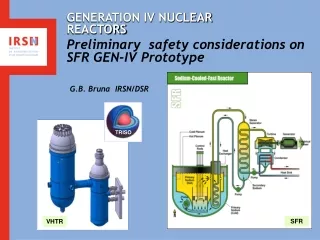
GENERATION III REACTORS EXTERNAL AND INTERNAL HAZARDS. Céline PICOT IRSN. 18 12 13. OBJECTIVES AND TERMS OF REFERENCE. Key words EPR : European Pressurized Reactor SSCs : Structures, Systems and Components NPP : Nuclear Power Plant Objectives

E N D
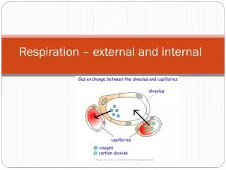
GENERATION III REACTORSEXTERNAL AND INTERNAL HAZARDS • Céline PICOT • IRSN • 18 12 13
OBJECTIVES AND TERMS OF REFERENCE • Key words • EPR : European Pressurized Reactor • SSCs : Structures, Systems and Components • NPP : Nuclear Power Plant • Objectives • General approach for protection against external and internal hazards • Load cases and load combinations rules Gen III Reactors – External and internal hazards 18th December 2013
SUMMARY • General principles • External hazards • Internal hazards Gen III Reactors – External and internal hazards 18thDecember 2012
SUMMARY • General principles • External hazards • Internal hazards Gen III Reactors – External and internal hazards 18thDecember 2013
Safety principles • GENERAL SAFETY OBJECTIVES • A significant reduction of the global core melt frequency must be achieved for the nuclear power plants of the next generation. Implementation of improvements in the "defence-in-depth" of such plants should lead to the achievement of a global frequency of core melt of less that 10-5 per plant operating year, uncertainties and all types of failures and hazards being taken into account (Technical Guidelines - Section A1.1). • SAFETY DEMONSTRATION • Complementary to the single initiating events, the safety demonstration has to analyze multiple failure situations as well as internal and external hazards. The safety demonstration with respect to these situations and hazards can be supported by probabilistic assessments. Possible links between internal and external hazards and single initiating events have also to be considered (Technical Guidelines - Section A1.4). Gen III Reactors – External and internal hazards 18th December 2013
Safety principles • Protection against internal hazards • The "defense-in-depth" principle has to be applied to the protection against internal hazards so as to limit the likelihood and the consequences of such hazards by the implementation of prevention, control and mitigation provisions, consistently with provisions for internal events (Technical Guidelines - Section A2.4). • Protection against external hazards • External hazards must not constitute a large part of the risk associated to nuclear power plants of the next generation (Technical Guidelines - Section A2.5). Gen III Reactors – External and internal hazards 18th December 2013
SUMMARY • General principles • External hazards • Internal hazards Gen III Reactors – External and internal hazards 18th December 2013
External hazards:Definition and general principles • Definition • Natural or man-induced events originated outside the plant with the potential of adversely affecting the safety of the plant. • General principles • Nature and level depend on the site under consideration. Their cause is located out of the plant site. • For a determined location, the designer can characterize external hazards but it is generally not possible to act on their causes. • External hazards can potentially affect the safety of the plant and/or induce damages to • heat sink • outside power (risk of Loss Of Outside Power). • They must be taken into account in the design and in the safety demonstration. Gen III Reactors – External and internal hazards 18th December 2013
External hazards: Nature of external hazards • External hazards to take into account in EPR plant design and safety demonstration • Earthquakes • Airplane crashes • External explosions • Extreme weather conditions (water & air temperatures, wind, …) • Lightning and electromagnetic interferences • Rises in the ground-water table • External flooding • Drought (low level of heat sink) • Ice formation • Toxic, corrosive or flammable gases • Other externally generated hazards (pollution of the heat sink by hydrocarbons or marine organisms, coastal erosion…) Gen III Reactors – External and internal hazards 18th December 2013
General objectives for external hazards (1/2) Protection of EPR against external hazards relies on the definition of loads combinations for structures, equipment & systems that must withstand such loadings. The deterministic dimensioning of the structures and equipment is made according to these load combinations. • The load case approach aims at decoupling : • the study of the hazard itself and the study of plant process, • the study of the hazard, and other internal or external hazards Gen III Reactors – External and internal hazards 18th December 2013
General objectives for external hazards (2/2) For some external hazards, the load case approach is supplemented by an event-based approach. The event-based approach aims at verifying that safety objectives are achieved when a total decoupling between the study of the hazard itself and the study of plant process is not achieved by design. Gen III Reactors – External and internal hazards 18th December 2013
Design characteristics The EPR design offers specific characteristics providing a good robustness regarding external hazards (such as earthquakes or airplane crashes): • some buildings are protected by an external structure designed against airplane crashes • some buildings are protected by geographical separation (interesting for hazards affecting only a part of the plant) • common basemat for the buildings of the Nuclear Island Gen III Reactors – External and internal hazards 18th December 2013
EPR protection: general arrangement Gen III Reactors – External and internal hazards 18th December 2013
EPR protection: General arrangement Gen III Reactors – External and internal hazards 18th December 2013
EARTHQUAKES The identified risk Unavailability of the equipment necessary to return and maintain the plant in a safe state due to their specific strength capacity and/or to adjacent equipment or to other hazards induced by the earthquake, Objective of protection against earthquakes Following an earthquake, the objective is to ensure that the safety functions of the systems and components necessary to return and maintain the plant to safe shutdown state will not be unacceptably affected. The approach for protection against earthquakes is deterministic. Gen III Reactors – External and internal hazards 18th December 2013
EARTHQUAKES: Design (1/3) For Seismic Classified civil works, the design is realized using specific site conditions, i.e. specific soil characteristics and spectra. 2 levels of earthquake are used for Flamanville EPR: the Standard Design Earthquake : EUR 0.25 g design spectra associated to hard soil conditions The Standard Design Earthquake is used for the design of seismic classified buildings (safeguards buildings 1 to 4, fuel building, inner and outer containment walls, concrete and steel internal structures). the Site Design Earthquake : EUR 0.15 g design spectra associated to hard soil conditions The Site Design Earthquake is used for the design of seismic classified site buildings. Gen III Reactors – External and internal hazards 18th December 2013
EARTHQUAKES: Design (2/3) The design and qualification of Seismic Classified equipment of the standard part of the plant relies on a set of standardized conditions : EUR 0.25 g design spectra associated to standardized soil conditions The standardized soil conditions were anticipated to envelope the soil conditions of any potential site in France. For any civil work structure or equipment, these seismic parameters (spectrum, level and soil conditions) constitute the two horizontal components of the Design Earthquake. Gen III Reactors – External and internal hazards 18th December 2013
EARTHQUAKES: Design (3/3) The Design Earthquake taken into account for EPR is more severe than the one of French existing NPP Gen III Reactors – External and internal hazards 18th December 2013
EARTHQUAKES: Seismicclassification • Seismic class 1 (SC1) corresponds to : • Equipment and construction works which house or fulfill F1 functions (i.e. needed to reach the controlled state or the safe shutdown state) • Equipment which is B1 classified (i.e. non isolable barrier likely to contain largely contaminated fluid or to release high radioactive fluid in case of failure) • Equipment for which capabilities are required in case of Design Earthquake • The requirements for seismic class 1 are : • operability during or after an earthquake • functional capability • integrity • Stability • Seismic class 2 (SC2) corresponds to equipment and construction works which must protect or which could inadmissibly impact seismic class 1 equipment. • The requirements for seismic class 2 are : • integrity • and/or stability 18th December 2013
EARTHQUAKES: Inspection earthquake • The Inspection Earthquake • represents • the earthquake level below which no particular verification is necessary • It corresponds to a maximum horizontal free field floor acceleration of 0.05g • In case of overstepping of the maximum acceleration corresponding to the Inspection Earthquake, further analyses are necessary to analyse whether the facility has been loaded outside the elastic range and whether it is still in its normal operating conditions. Gen III Reactors – External and internal hazards 18th December 2013
EARTHQUAKES: Loadcombinations • Combination of the loadings resulting from a Design spectrum with those resulting from the Loss of Coolant Accident for the dimensioning of the inner containment and internal structures • Combination of the loadings resulting from the Design spectrum with those resulting from PCC-2 to 4 for the dimensioning of seismic class 1 equipment (criteria associated to PCC-4 events) Gen III Reactors – External and internal hazards 18th December 2013
EARTHQUAKES: Safetyanalysis • Consistency of the design with regard to site conditions Consistency is verified through the comparison between the load cases taken into account for the design of civil work structures and equipment and the characteristics of the Increased Safety Earthquake defined for the site • Earthquake specific plant verification : earthquake as an event Identification of non-seismic class 1 equipment whose failure (one or multiple failures) could damage a seismic class 1 equipment item or could prevent achieving the safety objectives • Specific analysis of a set of PCC 2 to 4 A specific analysis is performed for the PCC 2 to 4 assuming a conventional combination with Loss of Outside Power as a result of the earthquake. • Verification of safety margins A verification is carried out for each site to verify that the design bases adopted (choice of the seismic level, conservatisms of the approach…) together with the plant protection from earthquakes, confer on the plant margins with respect to the earthquake-related safety objectives. Gen III Reactors – External and internal hazards 18th December 2013
EXTERNAL FLOODING Risks • water ingress in buildings housing the equipmentnecessary to return and/or maintain the plant in a safe state due to overflooding of the platforms or to ground-water rising • damages to the pumping station or clogging due to the debris carried by rivers in spate (branches of trees…) • damages to external electrical supplies due to submersion of interconnection stations, instability of electricity pylon or damages to electrical wires SdM I N SdP Gen III Reactors – External and internal hazards 18th December 2013
EXTERNAL FLOODING: Lessons learnt from the Blayais event Le Blayaisflooding: • Many areas were flooded, some containing safety-related equipment • All the units were more or less affected • Potential risk of loosing all the external electrical supplies • Extreme meteorological conditions • Insufficient level and shape of the protection dykes • Temporary site inaccessibility: problems with on-site organization • Inadequate warning system • Difficulties with the application of procedures The partial flooding of « Le Blayais » Nuclear Power Plant has called into question the design bases used for the protection against external flooding and the existing measures. In the light of the observations made during this flooding, a wide "review project" of investigations aiming to ensure that the installations would be effectively protected against external flooding and based on a more comprehensive methodology has been achieved. • Experience feedback of the Le Blayais partial flooding is included in the design of EPR Gen III Reactors – External and internal hazards 18th December 2013
EXTERNAL FLOODING: Safety approach of protection of EPR SAFETY OBJECTIVES • Ensure the integrity of the main primary system • Stop the reactor and evacuate the residual power • Limit any possible release of radioactive substances to an acceptable level LOAD COMBINATIONS • Identification of the phenomena likely to generate an external flooding and characterization of a load case associated to each phenomenon, considering combinations of phenomena if needed. • In addition to combinations of phenomena, the following combinations are considered: • External flooding combined with a Loss Of External Power and / or External, • External flooding combined with an additional Total Loss of Coolant situation. Gen III Reactors – External and internal hazards 18th December 2013
(1) (2) (3) (4) (5) • The 1984 BSR defines requirements for river/estuary/marine water levels to consider in the design of French NPP. 5 phenomena are considered: • River flood • Dam failure • Tide • Storm surge • Tsunami EXTERNAL FLOODING: Phenomena identification Prior to le Blayais event : Basic Safety Rule (BSR) Atmosphere Water retaining structures Canal Water retaining structures Circuits Equipment River Estuary Sea Groundwater Gen III Reactors – External and internal hazards 18th December 2013
EXTERNAL FLOODING: Phenomena identification Blayais event feedback: Atmosphere Water retaining structures Canal Water retaining structures (8) (7) Circuits Equipments (1) (2) (3) (4) (5) River Estuary Sea (8) (6) (7) Groundwater necessity to take into account “complementary” phenomena: (6) Wind-waves on sea (7) Wind-waves on river or channel (8) Swelling due to operations on valves or pumps Gen III Reactors – External and internal hazards 18th December 2013
EXTERNAL FLOODING: Phenomena identification Atmosphere Water retaining structures Canal (11) (12) Water retaining structures (8) (7) Circuits Equipments (1) (2) (3) (4) (5) River Estuary Sea (9) (10) (9) (8) (6) (7) (13) Groundwater • New methodology 8 “complementary” phenomena • (6) Wind-waves on sea • (7) Wind-waves on river or channel • (8) Swelling due to operation on valves or pumps • (9) Water retaining structures (other than dams) deterioration • (10) Circuits or equipment failure • (11) Rainfalls on site, brief and intense • (12) Rainfalls on site, regular and continuous • (13) Groundwaterrising Gen III Reactors – External and internal hazards 18th December 2013
EXTERNAL FLOODING: Combinations of phenomena Examples of combinations taken into account for the protection of a coastal site against external flooding: • Exceptional flood (Safety-Increased Maximum Water Level) combined with a hundred-year swell, • A hundred-year coastal flood (including an excess of water level and a high tide) combined with a hundred-year Regular Continuous Rain, • Exceptional flood (Safety-Increased Maximum Water Level) combined with a ten-year Regular Continuous Rain for 24 hours (as part of defence in depth), • Exceptional flood (Safety-Increased Maximum Water Level) combined with swelling (stoppage of circulating water pumps), • Seawater submersion (Safety-Increased Maximum Water Level) combined with groundwater at the maximum historical level. Flooding induced by an earthquake: • Deterioration of water channel structures • Failures caused by earthquakes affecting non-seismic equipment located on the platform (non-seismic tanks, piping…) Gen III Reactors – External and internal hazards 18th December 2013
EXTERNAL FLOODING: Design basis for protection • Platforms’ level • Definition of a watertight area (protection against rise in groundwater or defense-in-depth) • Design of drains network(protection against rainwater) • Fixed or mobile protection measures Gen III Reactors – External and internal hazards 18th December 2013
EXTERNAL FLOODING: Practical application for EPR-Flamanville 3 PF NI=12,4mNGFN • All additional phenomena considered after Blayais event have been covered in the design • Nuclear island platform 4,6 m above maximum sea level (SIMWL) • 75 cm margin above SIMWL for pumping station (climate change provision) • Water tight volume • Consideration of rupture of all non seismic qualified capacity on site. • Increased capacity of drain networks • Additional power supply • Design of the ultimate heat sink LFEWL=7,79mNGFN • LFEWL = maximum tide (coeff120) + 1000 yearexcessof water level Gen III Reactors – External and internal hazards 18th December 2013
EXTREMELY HIGH TEMPERATURES • taken into account in the design of the equipment • For an operating life of 60 years: 100-year return level taking into account predictions of climate changes • 3 temperatures for EPR standard design: • Daily Maximum air temperature (and the associated relative humidity) • defined in order to protect safety components, equipment and systems located in high thermal inertia buildings (those equipped with ventilation and cooling systems). • defined as the 100-year return level of 12h-mean temperature • Instantaneous Maximum Air temperature (and the associated relative humidity) • For external material and low thermal inertia buildings • defined as the 100-year return level of daily maximum temperature • Daily Maximum cooling water temperature : 26°C Gen III Reactors – External and internal hazards 18th December 2013
LOW AIR TEMPERATURES • are not taken into account in the design of equipment but considered under the protection against external hazards • 3 temperatures for EPR standard design: • Long-term temperature: • represents conditions that may occur frequently (normal and permanent). • determined like the minimum of the average temperature during 7 consecutive days with a 50-years return level - 15 °C • used for the of civil works design • Short-term temperature: • representative of a temperature that may occur for limited periods both in time and in frequency. • determined like the minimum of the daily average temperature, with a 100-years return level - 25 °C (with -4°C margin) • used to design ventilation systems and protection against freezing • Instantaneous minimal temperature: • replaces the short time temperature for equipment with low thermal inertia. • -35°C with -5°C margin Gen III Reactors – External and internal hazards 18th December 2013
LOW AIR TEMPERATURES Gen III Reactors – External and internal hazards 18th December 2013
AIRPLANE CRASH • French existing plants are protected against the general aviation • EPR is also protected against the military aviation (20 tons, 215 m/s) through: • a protective shell for the reactor building, the fuel building and two of the safeguard system buildings (divisions 2 and 3) • a geographical separation of the two other safeguard system buildings (divisions 1 and 4) and of the diesel buildings Gen III Reactors – External and internal hazards 18th December 2013
Protection of EPR against external hazards generally relies on a load-case oriented approach.Some of the load cases taken into account for EPR are more severe than the those of existing French NPP (earthquakes, airplane crashes, explosions). The others are equivalent to those of existing French NPP.An approach has been developed to identify combinations of external hazards and internal events or other hazards to take into account in the design in accordance with the general safety objectives of EPR.For some hazards depending on climatic conditions (flooding, water and air temperatures), additional allowances are taken into account and the design allow later adaptations to reinforce the protection in the event of climate change higher than expected at the design stage. Conclusion about protection of EPRagainst external hazards Gen III Reactors – External and internal hazards 18th December 2013
SUMMARY • General principles • External hazards • Internal hazards Gen III Reactors – External and internal hazards 18th December 2013
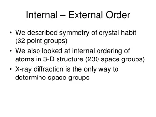
Internal hazards: General principles • Their origin is located on the plant site • It is possible to act on their causes (≠external hazards). • Internal hazards can potentially lead to a common cause failure within the systems used to reach or maintain the plant in a safe state. • must be taken into account in the design and in the safety demonstration. Internal hazards to take into account in EPR plant design and safety demonstration: • Ruptures in high energy piping, tanks, pumps and valves • Internal flooding • Fire • Missiles and internal explosions • Dropped loads. Gen III Reactors – External and internal hazards 18th December 2013
Internal hazards: General approach Protection of EPR against internal hazards relies on: • design characteristics • installation rules and/or internal measures for each affected buildings • at the end of the design, safety analysis must be carried out to verify plant resistance to internal hazards, using rules similar to those for initiating events (single failure, time for mitigation action). • PSA’s Gen III Reactors – External and internal hazards 18th December 2013
Internal hazards: Safety requirements (1/2) • The aim is to sufficiently protect the equipment needed for the main three safety functions. • General rule for internal hazards: the design must be such that internal hazards : • do not prevent F1(*) functions to be performed, even if generally not needed after such an event • do not trigger a PCC-3 or 4 event • do not impair divisional separation • The habitability of the Main Control Room (MCR), shall not be impaired by an internal hazard. • In case of inaccessibility of the MCR, the habitability of the Remote Shutdown Station (RSS) shall be ensured. Furthermore, accessibility to perform local actions shall be ensured, if necessary. (*) F1 functions : functions required to reach the controlled state or the safe shutdown state (**) PCC-3 : design basis incident; PCC-4 : design basis accident Gen III Reactors – External and internal hazards 18th December 2013
Internal hazards: Safety requirements (2/2) According to these requirements, an internal hazard shall not impair: • more than one redundancy of F1 systems • the stability/integrity of: • Reactor Coolant Pressure Boundary (except in case of LOCA) • Reactor internals including the fuel elements, • Main steam and feedwater pressure boundary, • Fuel pool and its internal structures, including the fuel elements, • Safety classified buildings and fire barriers, • Components whose failure is excluded by design, e.g. Break preclusion piping Gen III Reactors – External and internal hazards 18th December 2013
Internal hazards: Design characteristics • each train of the safety systems is protected against spreading of Internal Hazards from one train to any other. This requirement leads to an allocation of each train into a specific area (division), which is separated from the other trains. According to the number of trains, the 4 Safeguard Buildings correspond to the four safety divisions • some buildings are protected by geographical separation • the Spent Fuel Pool is integrated into the Fuel Building also separated from the safety divisions. If the internal hazard occurs in a safeguard or diesel building, its consequences should be limited to the concerned division If the internal hazard occurs in another building (containment, fuel building…), the design should ensure that no more than one redundancy of each F1 system is affected. Gen III Reactors – External and internal hazards 18th December 2013
Div. 3 Div. 4 Div. 2 Div. 1 Internal hazards: Design characteristics Gen III Reactors – External and internal hazards 18th December 2013
Internal hazards: Safety analysis Internal hazards are considered with a deterministic approach. Nevertheless, a probabilistic assessment can be performed for some hazards. The analysis must demonstrate that the plant can be brought to the safe shutdown state. The single failure shall be applied in the analysis of internal hazards not leading to accidents, leading to PCC-2 events or resulting from PCC-3 or 4 events The preventive maintenance of systems should also be taken into account for the same kinds of internal hazards For internal hazards resulting from RRC-A or RCC-B events, neither single failure or preventive maintenance are considered Gen III Reactors – External and internal hazards 18th December 2013
INTERNAL FLOODING Identification of the risks Internal flooding may damage equipment or civil work structures, or prevent equipment operation Potential initiators • Leaks and breaks in pressure retaining components • Erroneous alignment • Flooding by the water arriving from neighboring buildings • Spurious actuation of the fire fighting system, use of mobile fire fighting equipment • Overfilling of tanks • Consequences of failures of isolating devices 18th December 2013
INTERNAL FLOODING: SAFETY ANALYSIS The internal flooding safety analysis aims at providing the deterministic demonstration that the plant has an acceptable protection against this hazard. The demonstration shall be performed after the end of the detailed design, for each safety classified building. An initiation of flooding shall be postulated in each room for each relevant type of initiator. To evaluate the consequences: use the analysis rules and the assumptions below: • All mentioned initiators shall be considered. Only one of them is supposed to occur at the same time, unless two or more may have an identified common cause; • The flooding is supposed to happen during normal operation of the plant (under power operation or during shut down); • A release duration is postulated, depending on the possibilities of detection of the leak/break and depending on the possibilities and type of isolation (automatic or manual isolation, from the main control room or by local actions…). • The following equipment or structures are liable to fail by flooding: • All electrical and I&C equipment, except cables whose endings are not flooded and other waterproof equipment, • Some parts of civil works structures if they are not able to withstand pressure or temperature of the flooding, • All not waterproof mechanical equipment. Gen III Reactors – External and internal hazards 18th December 2013
. Conclusion about protection of EPRagainst internal hazards • Internal hazards taken into account with a deterministic approach • The design (4 safety trains, 4 divisions, geographical separation) provides a good robustness regarding internal hazards • Safety analysis will be carried out to verify plant resistance to internal hazards, using rules similar to those for initiating events (preventive maintenance, single failure, excepted for hazards induced by RCC-A or RCC-B events) Gen III Reactors – External and internal hazards 18th December 2013
Thank you for your attention Gen III Reactors – External and internal hazards 18th December 2013