Download
1 / 43
450 likes | 577 Vues
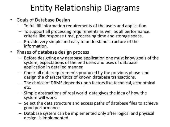
Entity Relationship Diagrams. Goals of Database Design To full fill information requirements of the users and application. To support all processing requirements as well as all performance. criteria like response time, processing time and storage space.

E N D
Entity Relationship Diagrams • Goals of Database Design • To full fill information requirements of the users and application. • To support all processing requirements as well as all performance. criteria like response time, processing time and storage space. • Provide very simple and easy to understand structure of the information. • Phases of database design process • Before designing any database application one must know goals of the system, expectations of the end users and uses of database application in detailed manner. • Check all data requirements produced by the previous phase and design the characteristics of known database transactions. • The choice of DBMS depends upon factors like technical, economical etc. • Simple abstractions of real world data gives the idea of how the system will work. • Select the data structure and access paths of database files to achieve good performance. • Database system can be implemented only after logical and physical design is implemented.
ER Model • In 1976 Chen developed the Entity Relationship (ER) model a high level data model that is useful in developing a conceptual design for a database. • Constructing ER diagram is a first step in designing a database. • ER model defines the data elements and relationships among them. • ER data model is based on perception of real world data consisting of entities (data items) and relationships among those entities. • Popular high level conceptual model used for conceptual design of database.
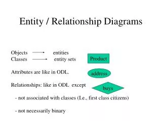
ER Diagrams • Uses ER model for solving design problems. • Diagrammatic notation associated with ER model. • Consists of Entity, Attributes and Relationships. • Diagrams/Notations used in ER diagrams • Rectangle entity sets • Ellipses attributes • Diamonds relationship sets • Lines link attributes to entities and entities with entities • Double Lines indicates total participation of an entity in a relationship • Double Rectangles weak entity sets
Entities • A fundamental component of ER model. • It is a thing in real world with its own independent existence. E.g. Student, Faculty • May be an object with physical or logical existence. • Has its own properties that describe the entity known as attributes. • Entity Set • Collection of all entities of same type • Strong Entity – Entity type having own distinct primary key by which we can identify specific entity uniquely. E.g. Empno in Emp table, RollNo in Student table. Represented by single rectangle • Weak Entity – Entity type which cannot form distinct primary key from their attributes. These type of entities are dependent on strong entity for primary key. Some weak entities contain virtual primary key called as Discriminator. Represented by double rectangle
Attributes • Various properties that describes an entity • Attribute value that describes each entity becomes a major part of data stored in database as each entity will have some value for each of its attributes. • E.g. Employee entity has name, age, phone etc. as attributes. • Simple Attributes • Which cannot be divided into sub parts E. g. Salary of employee • Composite Attributes • Which can be divided into sub parts E.g. Name can be divided into FirstName and LastName • Single Valued Attribute • Having atomic (only one) value for particular entity. • E.g. Student has only one roll no • Multi Valued Attribute • Many values for a particular entity • E.g. Employee has multiple mobile numbers
Attributes Contd • Stored Attributes • Simple attributes stored in database • E.g. DateOfJoin for Employee • Derived Attributes • Value of this attribute is derived from value of related stored attribute • E.g. EmployeeTenure can be calculated from DateOfJoin • Null Attribute • Can take a null value when entity does not have a value for it or the value is unknown. • E.g. Commission attribute in Employee table specifies whether the Employee has commission or not • Key Attribute • Must have a unique value by which any row can be identified. • E.g. Deptno for department table
Relationships • An association among several entities • Use diamond to illustrate in ER diagrams and read from left to right • Degree • Number of participating entities in a relation • Relationship Set • Collection of all relationship of same type Works For Employee Department
Constraints on Relationships • Mapping Constraints / Cardinalities • Number of entities to which another entity is associated. • Type • ONE to ONE – One tuple in entity is related only with one tuple in another entity. One department can have only one manager. • ONE to MANY – One tuple in entity is related with many tuples in another entity. One department can have many employees. • MANY to MANY – Many tuples in entity is related many tuples in another entity. Books in library issued by students
Constraints On Relationships Contd • Participation Constraints • Total Participation • Every object in an entity must participate in relationship. • Indicated by dark or double line between entity and relationship. • Every department must have manager. • Partial Participation • More than one object in an entity may participate in a relationship. • Indicated by single line between entity and relationship. • Employee works for department.
Extended Entity Relationship Model – ERD Issues • EER model includes all modeling concept of ER model • In addition it includes the concept of specialization and generalization • EER model is used to represent collection of objects that is union of objects of different entity types • A diagrammatic technique for displaying the EER concepts is called as EER diagrams
Sub Class – Super Class And Inheritance • Super Class • The class has its sub groupings • An entity cannot exist in database merely by being member of any super class • Sub Class • A sub grouping of super class • More specific version of super class • Inherits properties and attributes from its super class • Super Class And Sub Class Relationship • Relationship between super class and sub class is called SuperClass/SubClass relationship • Shown by encircled • Leads to concept of Inheritance d
Sub Class – Super Class And Inheritance Contd • Inheritance • Important concept associated with subclass • Type of an entity is defined by an attribute poses by a relationship types in which they participates • Entity in subclass represent entity from upper class it should poses value for specific attribute as member of super class • Entity represents all relationships in which super class participates • Entity that is the member of subclass inhabits all attributes of entity as a member of super class
Specialization And Generalization • Specialization • Top down approach of superclass/ subclass relationship. • Process of defining a set of subclass of entity type is also called as super class of specialization. • Set of subclasses that forms a specialization is defined on the basis of some distinguishing characteristic of entity in super class. • E.g. Set of subclass (Saving_Account, Current_Account) are specialization of superclass Account. • The subclass defined n specialization is attached by lines to a circle which is connected to super class. • Subset symbol on each line connecting a subclass to circle indicates the direction of super class/ subclass relationship. • An attribute applied only to entities of particular subclass is called as specific attribute.
Generalization • Reverse process of specialization or bottom up approach of super class/ subclass relationship • Process in which we differentiate among several entity types identifying their common features and generalizing them into single super class of which original entity type are special subclasses • E.g. Car and Bike do have several common attributes that can be generalized to super class vehicle • In diagrammatical notation arrow pointing to generalized super class represents generalization and arrow pointing to generalized subclass represents specialization • Attributes created of higher or lower level entities are attributes inheritance
Codd’s Rule • Information Rule – All available data in system should be represented as relations or tables. • Guaranteed Access Rule – Each data item must be accessible without ambiguity by providing table name and its primary key of the row also include its column name to be accessed. • Systematic Treatment of Null Values – Null values are not equal to blank space or zero they are unknown unassigned values which should be treated properly. • Self Describing Database – There should be dynamic online catalog based dictionary on relational model which keep information about tables data in database • Comprehensive Data Sublanguage – The data access language (SQL) must be the only means of accessing data stored in the database and support DML, DDL etc. • View Updating Rule – All views of data are theoretically updateable & can be updated using system.
High Level Insert, Update & Delete – This rule states that in a relational database , the query language must be capable of performing manipulations on sets of rows in a table. • Physical Data Independence – Any changes made in the way is physically stored must not affect applications that access data. • Logical Data Independence – This rule states that changes to the database design should be done in a way without the users being aware of it. • Integrity Independence – Data integrity constraints which are definable in the language must be stored in the database as data in table is, in the catalog and not in the application program. • Distribution Independence – In a RDBMS data can be stored centrally that is on a system or distributed across multiple systems. • Non Subversion Rule – This rule states that there should be no bypass of constraints by any other languages.
Relational Database Model • First proposed by Dr. E. F. Codd hence known as father of relational model. • Was an attempt to simplify database structure by making use of tables and columns. • Collection of 2-dimensional tables having unique names which consists of rows and columns. • Tables are known as relations columns are known as attributes and rows or records are known as tuples. • A row in a table represents a relationship among a set of values. Thus a table represents a collection of relationships.
Logical View Of Data : Table (Relation) • Introduction • Tables / Relations are logical structure which is a collection of 2-dimensional tables consisting of horizontal rows and vertical columns. • It is an abstract concept and do not represent how data is stored in physical memory of computer system. • Each table in database has its own unique table name by which its contents can be referred.
Logical View Of Data : Table (Relation) • Characteristics • A table is perceived as 2-dimensional structure composed of rows and columns. • Each table row(tuple) represents a single entity occurrence within the entity set. • Each table column represents an attribute and each column has a distinct name. • Each row/column intersection represents a single data value. • All values in a column must confirm to the same data format. • Each column has specific range of values known as attribute domain. • The order of the rows and columns is immaterial to DBMS. • Each table must have an attribute or a combination of attributes that uniquely identifies each row.
Logical View Of Data : Table (Relation) • Attributes • Each column in the table represents one data item stored in it database for that table • Such column in database is called as attribute of a table • Tables must have at least one column in it and no two columns can have same name • The ANSI/ISO SQL standard does not specify a maximum number of columns in a table • Tuple/Records • A single row or tuple contains all the information about a single entity • Each horizontal row of the table represents a single entity • A table can have ay number of rows from zero to thousand • If number of rows are zero then it is called as empty table
Key • The column value that uniquely identifies a single record in the table is called as KEY of table • An attribute or set of attributes whose values uniquely identify each entity in an entity set is called as key for that entity set • Any key consisting of single attribute is called a simple key while that consisting of a combination of attributes is called a composite key
Types Of Keys • Super Key – A key attribute with additional attributes that uniquely identifies a single record in a table. • Candidate Key – Super key without its unnecessary attributes. • Primary Key – Column or combination of columns whose values uniquely identify a single row in that table. • Secondary Key – Column or combination of columns used for data retrieval process. • Foreign Key – A column or collection of columns in one table must match the primary key in some other table. This link is also called as referential integrity.
Integrity Rules • Entity Integrity – All primary key entries are unique and no part of primary key may be null. Each row will have unique identity and foreign key values can properly reference primary key values • Referential Integrity – It can have a null entry as long as it is not a part of its tables primary key or an entry that matches the primary key value in a table to which it is related. It is possible for an attribute NOT to have a corresponding value but it will be impossible to have an invalid entry. The enforcement of referential integrity rule makes it impossible to delete a row in one table whose primary key has mandatory matching foreign key values in another table • Not Null – As per requirements there are some values which should not be having any NULL value • Unique – In this case no two tuples can have equal value for same attribute • Check – Define own integrity rule using CHECK constraint
Features Of Good Relational Database Design - Normalization • Step by step decomposition of complex relational tables into simple table • Results in tables that represented in a simple manner and satisfy some constraints • Avoids data redundancy by applying some constraints on data to avoid various data anomalies • A normalized table is less vulnerable to data problems • Process of designing a consistent database by minimizing redundancy and ensuring data integrity through the principle of non-loss decomposition
Goals Of Normalization • Ensures Data Integrity • Data integrity ensures the correctness of data stored within the database and can be achieved by imposing data integrity rules. An integrity rules restricts values present in the database • Prevents Redundancy • A non normalized data is stored in different locations and hence modification makes data inconsistent. A normalized data stores data only in one place. Direct redundancy can result due to presence of same data in two different locations . Indirect redundancy results due to storing information that can be computed from the other data items stored within the database • Data Anomalies • Update Anomaly – Same information can be present in multiple records of various tables hence update to only one table will result in inconsistency • Insertion Anomaly – There is a possibility in which certain facts cannot be recorded at all or that are not yet recorded • Deletion Anomaly – Deletion of some data from a relation necessitates the deletion of unrelated data also
Disadvantages Of Normalization • Increases number of relations • As normalization involves the decomposition of relations into multiple relations or tables hence higher degrees of normalization typically involve more tables. Therefore if highly normalized tables are used in database applications then the application becomes complex • Reduces performances • Higher degrees of normalization involve more tables and create the need for a larger number of joins which can reduce performance • Some redundancies are unavoidable. While normalizing the tables data integrity should not be compromised
Normal Forms • Forms are designed to logically address potential problems such as inconsistencies and redundancy in information stored in the database. • A database is said to be in one of the Normal Forms if it satisfies the rules required by that form as well as the previous form and it will also not suffer from any of the problems addressed by the form • Types Of Normal Forms • First Normal Form (1NF) • Second Normal Form (2NF) • Third Normal Form (3NF) • Boyce Codd Normal Form (BCNF) • Fourth Normal Form (4NF) • Fifth Normal Form (5NF)
First Normal Form (1NF) • A relation is in 1NF if every contains exactly one value for each attribute. • 1NF states that attributes included in relation must have atomic values and that any attribute in tuple must have a single value from the domain of that attribute. • The above table does not have any atomic values in the Subject column , hence it is in un normalized form. • The above table in 1NF will be as follows.
Second Normal Form • A relation is in 2NF if it is in 1NF and every non-key attribute is fully functionally dependent on primary key of the relation and not just part of the primary key • 2NF prohibits partial dependencies. • Steps • Find and remove attributes that are related to only a part of the key • Group the removed attributes in another table • Assign the new table the key that consists of that part of the old composite key • Hence in our example we will have two tables • Faculty (Faculty Code, Faculty Name, Date Of Birth) • Subject (Faculty Code, Subject, Hours) • Anomalies • Inserting records of various faculties teaching the same subject results in redundancy of hours information • As number of hours is repeated any change done has to repeated for every instance • If a faculty leaves the organization information regarding the subject is also lost
Tables would look like, • Faculty Table: Subject Table:
Third Normal Form • This normal form is used to reduce transitive dependency. • If A is dependent on B and B is dependent on C then A is said to transitively dependent on C. • A relation is in 3NF if it is in 2NF and no non-key attribute of the relation is transitively dependent on the primary key. • For a table to be in 3NF transitive dependency must be removed. So the 3NF table becomes • Faculty_Subject (Faculty Code, Subject) • Subject_Hours (Subject, Hours) • Advantages • No redundancy of data for subject and hours while inserting records • Subject and hours are stored in separate table so Updation becomes easier • Even if faculty record is deleted subject hours can still be retrieved
BCNF Normal Form • The intention of BCNF is that 3NF does not satisfactorily handle the case of a relation processing two or more composite or overlapping candidate keys • Candidate key is a column which has the ability to become a primary key • A determinant is any attribute on which some other attribute is fully functionally dependent • A relation is in BCNF if and only if every determinant is a candidate key • Consider the following table in which there is a dependency between (SoldierId + OfficerId) and UnitId. • There is also a dependency between UnitId and OfficerId which is not partial neither transitive • What we have is a table where a determinate is not a candidate key UnitId. This problem can be solved by BCNF
Introduction To UML • UML or Unified Modeling Language is a specification language that is used in the software engineering field • It can be defined as general purpose language that is used to design an abstract model which can be used in the system. This system is called UML model • UML is commonly used to visualize and construct software oriented systems. Because software has become much more complex nowadays, developers are finding it more challenging to build complex application within short periods of time • UML is specially proposed standard for creating specifications of various components of a complex software system
Types Of UML Diagrams • Class diagram • Most popular UML diagrams used for construction of software applications • Similar to E-R diagram • It is a static diagram • Shown using class as its basic entity and lines between them represents relationship between them • Describes the attributes and operations of a class and also the constraints imposed on the system • Use case diagram • Shows the interaction between users and the system in particular steps of tasks that users perform • Purpose is to capture the dynamic aspect of a system • Purpose is to gather requirements of a system and to identify external and internal factors influencing the system
Types Of UML Diagrams Contd • Activity diagram • Is basically a flowchart to represent the flow from one activity to another. The activity can be described as an operation of the system • It is a particular operation of the system • Are not only used for visualizing dynamic nature of a system but also used to construct the executable system by using forward and reverse engineering techniques • Implementation diagram • Are deployment diagrams which are used for describing about the hardware components where software components are deployed
Advantages And Disadvantages Of UML Diagrams • Advantages • It is the most useful method of visualization and documenting software systems design • It is effective for modeling large, complex software systems • It is simple to learn, but provides advanced features for expert analysts, engineers, designers and architects • It can specify systems in an implementation- independent manner • It specifies a skeleton that can be refined and extended with additional features • It specifies the functional requirements of system in an object oriented manner • Disadvantages • Still no specification for modeling of graphical user interface • Poor for distributed systems – no way to formally specify serialization and object persistence
Limitations Of Entity Relationship Model • One cannot represent relationship like inheritance in ER diagrams • No relationships is defined between entity type and relationship type • No relationship is defined between entity type and collection of entity type from which one may participate. E.g. EMPLOYEE is an individual entity where as it is set of entities in case of COMPANY database and hence we cannot show relationship between individual company and set of employees
Notations Used in ER Diagrams • Cardinality Ratio Notation • Use cardinality of each identity involved in relation • 1 (Exactly One Instance), M (Many Instances), N (Any Number Of Instances) specifies on each entity of binary relationship • Min-Max Notation • (Min , Max) notation represents entity is related to at least min, at most max relationship instance in relationship set
(Min,Max) notation relationship The constraints (0,1) (1,1) (1,1) Employee Department Department Manages (1,1) (1,N) (1,N) Employee Employee Department Department Works-for