Download
1 / 15
190 likes | 491 Vues
Chapter III Semiconductor Devices. 半導體元件. Basic Building Blocks of Semiconductor Devices. ( a) M-S Junction (b) P-N Junction (c) Heterojuction (d) MOS structure. Metal-Semiconductor Contact. Schottky contact Rectifying contact Schottky Barrier M-S devices Unipolar devices

E N D
Basic Building Blocks of Semiconductor Devices (a) M-S Junction (b) P-N Junction (c) Heterojuction (d) MOS structure
Metal-Semiconductor Contact • Schottky contact • Rectifying contact • Schottky Barrier • M-S devices • Unipolar devices • High-speed devices • Ohmic contact • Non-rectifying contact • Specific contact resistance • The apace charge width in a M-S contact is inversely proportional to the square root of the semiconductor doping.The probability of tunneling through the barrier increases with the increasing doping concentration. • Electrodes Energy-band diagram of a heavily doped n-semiconductor-to-metal junction
Schottky-Barrier Diode • M-S junction device • Unipolar device • Majority-carrier device • Without minority- carrier-storage effect • III-V compound semiconductors (GaAs) • Properities of devices: • High operation speed • Lower cut-in voltage • Higher saturation current
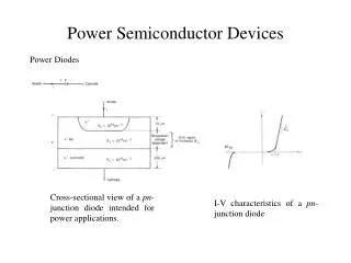
The P-N Diode --- Under Thermal Equilibrium P-type and N-type semiconductors before and after the junction formed A p-n junction with abrupt doping charges at the metallurgical junction
The P-N Diode --- Under Biasing Conditions Current-voltage characteristics of a typical Si p-n junction • Thermal equilibrium • Forward-bias condition. • Reverse-bias condition
Classification of Semiconductor Devices • Bipolar Devices • P-N Junction Diode • Bipolar Junction Transistor (BJT) • Heterojunction Bipolar Transistor (HBT) • Thyristor and related power devices • Unipolar Devices • Schottky-barrier diode (SBD) • Junction Field Effect Transistor (JFET) • Metal-Oxide-Semiconductor FET (MOSFET) • MOS Diode (Capacitor) • Complementary MOS (CMOS) BiMOS and BiCMOS • Power MOS • High-Speed Devices • Metal-Semiconductor FET (MESFET) • Modulation-Doped FET (MODFET), High-Electron-Mobility Transistor (HEMT)
Semiconductor Devices (continued) • Microwave Devices • Tunnel diode • IMPATT diode • Transferred-Electron Device (TED) • Quantum-Effect Devices • Hot-Electron Devices • Photonic Devices • Light Emitting Diode (LED) • Semiconductor Laser (Laser Diode, LD) • Photodetector • Photodiode (PD), Avalanche Photodiode (APD) • Phototransistor (PT) • Solar Cell • Display Devices • Thin-Film Transistor LCD (TFT-LCD) • Organic Electroluminescence Display (OELD) or Organic Light Emitting Diode (OLED)
Semiconductor Devices (continued) • Integrated Devices • Passive Components • IC Resistor, IC Capacitor, IC Inductor • MOS Menory • Dynamic Random Access Memory (DRAM) • Static Random Access Memory (SRAM) • Nonvolatile Memory • Erasable-Programmable Read-Only Memory (EPROM) • Electrically Erasable-Programmable Read-Only Memory (EEPROM) • Flash Memory • Single-Electron Memory • MEMS devices
MESFET Schottky Contact Ohmic Contact To minimize parasitic capacitances Mesa Structure
MODFET • Modulation Doped FET • A thin undoped well bounded by two wider bandgap doped barrier • HFET (Heterojunction FET) • 2DEG FET or TEGFET, • SEDFET (Separately Doped FET) • Advantages: • Extremely high cutoff frequency and fast access time
HEMT • HEMT: • High Electron Mobility Transistor • 250,000 cm2/V-s at 77K • 2,000,000 cm2/V-s at 4K • Why HEMT? • In conventional MESFET: Channel doping carrier number But mobility (impurity scattering) conductivity is limited ( = q n ) • For HEMT: Sheet carrier density is as high as 1012 cm-2 (~1020cm-3 for 10-nm thick channel layer)