Download
1 / 22
330 likes | 729 Vues
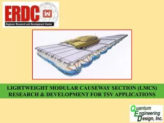
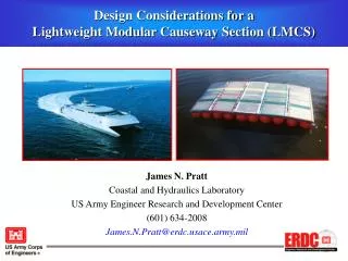
Design Considerations for a Lightweight Modular Causeway Section (LMCS). Jimmy E. Fowler Coastal and Hydraulics Laboratory US Army Engineer Research and Development Center (601) 634-3026 Jimmy.E.Fowler@erdc.usace.army.mil. JHSV Force Projection Enabler

E N D
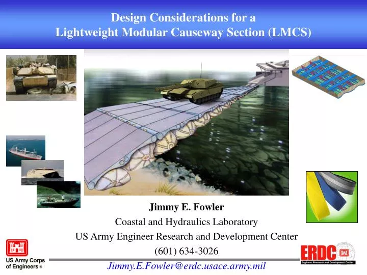
Design Considerations for a Lightweight Modular Causeway Section (LMCS) Jimmy E. Fowler Coastal and Hydraulics Laboratory US Army Engineer Research and Development Center (601) 634-3026 Jimmy.E.Fowler@erdc.usace.army.mil
JHSV Force Projection Enabler Needs causeway systems for austere SPODs
Existing Causeway Systems --- NLS, MCS, INLS --- all steel barge construction Not JHSV transportable or deployable
Desired LMCS Features • Transportable by and rapidly deployable from TSV/JHSV • Minimal storage/shipping volume • Tailorable to desired gap length • M1A2 payload • No in-water connections • Transportable by primary mover and air lift • Interface with existing JLOTS watercraft • Operational capabilities • - Sheltered ports and harbors • - Sea-state operations
TWO “NEW” CONCEPTS High-strength fiber connections: foldable maintains stiffness under tension adjustable compliancy Inflatable buoyancy reduces internal structure in deck minimizes storage volume adjusts to sloping bottom
Volume and Weight LMCS is expected to save 70% in weight and volume compared to existing MCS Causeway while retaining 100% of MCS payload capacity.
Transportability 36 tons – CH-53E Super Stallion Helicopter • Weight of system Air delivery may be limiting factor • Volume Stored and shipped configuration – less is best • ISO compatibility - MHE & Existing Military Prime Mover transportable 10ft 20ft 9ft
Deployability and Recoverability • TSV & JHSV on-board crane limitations • Weight and size • Equipment Requirements • Large Rigid Hull Inflatable Boat (RHIB) • Shore-based winch • Safety considerations • No in-water connections • Minimize assembly time • Minimize number of personnel • Simplify mooring system
JHSV Primary Deployment Option Deploy Unstiffened Units Draw units together and stiffen section (see details) • Continuous feed from rear of JHSV off ramp or rail system Deployment Boat or shore winch or anchor Lightweight deployment Ramp w/ floating support
Initially loosely connected by high strength straps/cables On board winch pulls sections together and sets design tension. Overall stiffness is combination of joint stiffness and module stiffness.
Survivability • Floatation • Resistance to puncture/abrasion • - Contact with sea/river bed • - Redundancy (2nd internal tube) • - Small punctures Slow pressure loss • Flat cable (strap) service life • - Material properties • Adjustable stiffness/compliance
Structural Stiffness Asymptotic to Zero Negative Deflection, inches Value for Current Design EI = 3.76E+10 lb-in^2 Asymptotic to Archimedes Depth 0 2 4 6 8 10 12 14 10
Effect of Cable Stiffness and Length Relative Shapes 60 Ft Cable 10 Ft Cables Solid
Floats Removed: 3 Even with 3 floats removed, positive freeboard is maintained
Structural Stiffness Full Scale Design All plate thicknesses except Main Beams = ¼ “ Main Beams: Plate Thickness = 1/2” Internal Stiffeners Stiffness is a function of strap properties End Plate End Plate Side Plate Bottom Plate Strap/Cable Conduits
Remained functional even with several pontoons damaged Treadway
MCS VS LMCS MCS LMCS Assembly time Number of personnel required for assembly Supporting equipment required Space & Weight
Structural Stiffness • Stiffened section length relative to total length • Strap characteristics • Breaking strength • Elasticity considerations • Shear/torsion rods