Download
1 / 35
1.05k likes | 4.27k Vues
THERMAL ENGINEERING (ME 2301 ). M.R.SWAMINATHAN Assistant Professor Department of Mechanical Engineering Anna University Chennai Chennai-25. DIESEL CYCLE .

E N D
THERMAL ENGINEERING(ME 2301 ) M.R.SWAMINATHAN Assistant Professor Department of Mechanical Engineering Anna University Chennai Chennai-25
DIESEL CYCLE The diesel cycle is the ideal cycle for CI (Compression-Ignition) reciprocating engines. The CI engine first proposed by Rudolph Diesel in the 1890s, is very similar to the SI engine, differing mainly in the method of initiating combustion.
In diesel engines, ONLY air is compressed during the compression stroke, eliminating the possibility of auto-ignition. Diesel engines can be designed to operate at much higher compression ratios, typically between 12 and 24.
The fuel injection process in diesel engines starts when the piston approaches TDC and continues during the first part of the power stroke. Therefore, the combustion process in these engines takes place over a longer interval.
Because of this longer duration, the combustion process in the ideal Diesel cycle is approximated as a constant-pressure heat-addition process. This is the ONLY process where the Otto and the Diesel cycles differ.
Thermal efficiency of Ideal Diesel Cycle Under the cold-air-standard assumptions, the efficiency of a Diesel cycle differs from the efficiency of Otto cycle by the quantity in the brackets.
The quantity in the brackets is always greater than 1. Therefore, hth,Otto > hth, Dieselwhen both cycles operate on the same compression ratio. Also the cuttoff ratio, rc decreases, the efficiency of the Diesel cycle increases.
BRAYTON CYCLE – GAS TURBINE The open gas-turbine cycle can be modeled as a closed cycle, as shown in the figure below, by utilizing the air-standard assumptions
BRAYTON CYCLE - PROCESSES 12 Isentropic compression (in a compressor) 23 Constant pressure heat addition 34 Isentropic expansion (in a turbine) 41 Constant pressure heat rejection
The highest temperature in the cycle occurs at the end of the combustion process, and it is limited by the maximum temperature that the turbine blades can withstand.
VALVE TIMING • Why valve Timing? • Is it significant? Yes Burning exact quantity of Air/Fuel mixture at right time and place produces more power output Moreover more economy and lesser emissions
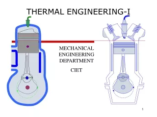
I.C.ENGINES External Combustion Engine A device where the working fluid is obtained indirectly e.g Steam or Locomotive boiler Coal is first burnt and then the heat energy obtained from coal is utilised to transform water to steam which is the working fluid. So the name External combustion engine just to differentiate from an I.C. engine
CLASSIFICATION OF I.C ENGINES Internal combustion engines are classified according to • Fuel used – D/P/G • Cycle of operation - O/Di/Du • Ignition system – SI / CI • Number of strokes – 2S / 4S • Type of cylinder arrangement – In / V/ H • Type of cooling – Air/Water
CLASSIFICATION OF I.C ENGINES • Speed of engine – L / M / H • Type of Lubrication • No. of cylinders – Single / multi
COMPONENTS OF I.C ENGINE • Cylinder Block • Part of engine frame that contains cylinders in which piston moves • Supports liners & head • Cylinder Head • Serves to admit, confine, and release fuel/air • Cover to cylinder block • Supports valve train • Crankcase • Engine frame section that houses the crankshaft
COMPONENTS OF I.C ENGINE • Piston • Acted on by combustion gases • Lightweight but strong/durable • Piston Rings • Transfer heat from piston to cylinder • Seal cylinder & distribute lube oil • Piston Pin • Pivot point connecting piston to connecting rod • Connecting Rod • Connects piston & crankshaft • Reciprocating (rotating motion)
COMPONENTS OF I.C ENGINE • Crankshaft • Combines work done by each piston • Drives camshafts, generator, pumps, etc. • Flywheel • Absorbs and releases kinetic energy of piston strokes (smoothes rotation of crankshaft) • Valves • Intake: open to admit air to cylinder (with fuel in Otto cycle) • Exhaust: open to allow gases to be rejected • Camshaft & Cams • Used to time the addition of intake and exhaust valves • Operates valves via pushrods & rocker arms
I.C ENGINE TERMINOLOGY • Bore is the diameter measurement of the cylinders in a piston engine • Stroke is a single traverse of the cylinder by the piston (from TDC to BDC) • 1 revolution of crankshaft = 2 strokes of piston • Compression Ratio is defined as the ratio of the volume of the cylinder at the beginning of the compression stroke (when the piston is at BDC) to the volume of the cylinder at the end of the compression stroke (when the piston is at TDC) • Common sparkignition compression ratio:6:1 to 12:1 • Common compression-ignition ratio: 16:1 to 23:1
Four stroke cycle • Intake stroke: intake valve opens while the piston moves down from its highest position in the cylinder to its lowest position, drawing air into the cylinder in the process. • Compression stroke: intake valve closes and the piston moves back up the cylinder. This compresses the air & therefore heats it to a high temperature, typically in excess of 1000°F (540°C). Near the end of the compression stroke, fuel is injected into the cylinder. After a short delay, the fuel ignites spontaneously, a process called auto ignition. • Combustion stroke: The hot gases produced by the combustion of the fuel further increase the pressure in the cylinder, forcing the piston down • Exhaust stroke: exhaust valve opens when the piston is again near its lowest position, so that as the piston once more moves to its highest position, most of the burned gases are forced out of the cylinder.