Download
1 / 53
530 likes | 536 Vues
Single-Area OSPF. Edited by Nour Alhariqi. 8.0. Outline. Link-State Routing Protocols Link-State Routing Process OSPF Configuration Loopback interface OSPF Configuration Mode OSPF router ID Enabling OSPF on Interfaces Wildcard Mask OSPF cost Reference BW Interface BW Verify OSPF.

E N D
Single-Area OSPF Edited by Nour Alhariqi 8.0
Outline • Link-State Routing Protocols • Link-State Routing Process • OSPF Configuration • Loopback interface • OSPF Configuration Mode • OSPF router ID • Enabling OSPF on Interfaces • Wildcard Mask • OSPF cost • Reference BW • Interface BW • Verify OSPF
Link-State Routing Protocols • In contrast to distance vector routing protocol operation, a router configured with a link-state routing protocol can create a complete view or topology of the network by gathering information from all of the other routers. • A link-state router uses the link-state information to createa topology map and to selectthe best path to all destination networks in the topology
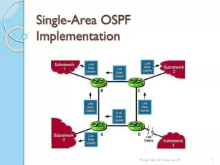
Link and Link-State The first step in the link-state routing process is that each router learns about its own links, its own directly connected networks.
Say Hello The second step in the link-state routing process is that each router is responsible for meeting its neighbors on directly connected networks.
Link State Updates The third step in the link-state routing process is that each router builds a link-state packet (LSP) containing the state of each directly connected link.
Flooding the LSP and Building the Link-State Database The fourth step in the link-state routing process is that each router floods the LSP to all neighbors, who then store all LSPs received in a database.
Computing the Best Path The final step in the link-state routing process is that each router uses the database to construct a complete map of the topology and computes the best path to each destination network.
AddingRoutes to the Routing Table • The best paths are inserted into the routing table
Loopback Interface • Loopback interface is a logical interface internal to the router. • It is not assigned to a physical port (not connected to any other device), it is considered a software interface that is automatically in an UP state. • Loopback interfaces are very useful because they will never go down, unless the entire router goes down. • This helps in managing routers because there will always be at least one active interface on the routers • Also it is important in the OSPF routing process.
Configure a Loopback Interface Any number between 0 and 2,147,483,647
Configuring Single-Area OSPFv2 • OSPFv2 is enabled using the global configuration mode command routerospf process-id. • The process-id value is locally significant, which means that it does not have to be the same value on the other OSPF routers to establish adjacencies with those neighbors any number between 1 and 65,535
Router IDs • Every router requires a router ID to participate in an OSPF domain. • The router ID can be defined by an administrator or automatically assigned by the router. • The router ID is used by the OSPF-enabled router to: • Uniquely identify the router • Participate in the election of the DR
Router IDs • But how does the router determine the router ID?
Router IDs • The router ID is explicitly configured using the OSPF router configuration mode command router-id rid. • The rid value is any 32-bit value expressed as an IPv4 address. • This is the recommended method to assign a router ID.
Router IDs • If the router ID is not explicitly configured, the router chooses the highest IPv4 address of any of configured loopback interfaces. • This is the next best alternative to assigning a router ID. The IPv4 address of the loopback interface should be configured using a 32-bit subnet mask (255.255.255.255).
Router IDs • If no loopback interfaces are configured, then the router chooses the highest active IPv4 address of any of its physical interfaces. • This is the least recommended method because it makes it more difficult for administrators to distinguish between specific routers.
Router IDs • Note: The router ID looks like an IP address, but it is not routable and, therefore, is not included in the routing table, unless the OSPF routing process chooses an interface (physical or loopback) that is appropriately defined by a network command.
Configuring an OSPF Router ID An OSPF router identifies itself to other routers using this router ID.
If the router ID is the same on two neighboring routers, the router displays an error message similar to the one below:
Modifying a Router ID • Sometimes a router ID needs to be changed. • However, after a router selects a router ID, an active OSPF router does not allow the router ID to be changed until the router is reloaded or the OSPF process cleared. • The reason is because the router already has adjacencies with other neighbors using the router ID. Those adjacencies must be renegotiated using the new router.
Clearing the OSPF process is the preferred method to reset the router ID. This forces OSPF on R1 to transition to the Down and Init states.
Single-area and Multiarea OSPF • OSPF allows the grouping of routers into a set, called an area.
Enabling OSPF on Interfaces • The basic command syntax is network network-address wildcard-mask area area-id • In single-area OSPF, area-id value is a same on all routers. • Although any area ID can be used, it is good practice to use an area ID of 0 with single-area OSPF.
Enabling OSPF on Interfaces • The network command determines which interfaces participate in the routing process for an OSPF area. • Any interfaces on a router that match the network address in the network command are enabled to send and receive OSPF packets. • As a result, the network (or subnet) address for the interface is included in OSPF routing updates.
Configure Single-area OSPFv2The wildcard mask calculates the wildcard mask from the network address of 192.168.10.0/24. culates the wildcard mask from the network address of 192.168.10.64/26. 8.2.2.2
The wildcard mask is typically the inverse of the subnet mask. • A wildcard mask is a string of 32 binary digits used by the router to determine which bits of the address to examine for a match. • In a subnet mask, binary 1 is equal to a match and binary 0 is not a match. • In a wildcard mask, the reverse is true: • Wildcard mask bit 0 - Matches the corresponding bit value in the address. • Wildcard mask bit 1 - Ignores the corresponding bit value in the address.
Enabling OSPF on Interfaces • As an alternative, OSPFv2 can be enabled using the command networkintf-ip-address 0.0.0.0area area-id • The advantage of specifying the interface is that the wildcard mask calculation is not necessary. • OSPFv2 uses the interface address and subnet mask to determine the network to advertise.
Configure Single-area OSPFv2The network Command • There are several ways to identify the interfaces that will participate in the OSPFv2 routing process.
Configure Single-area OSPFv2Configuring Passive Interfaces Use the passive-interface router configuration mode command to prevent the transmission of routing messages through a router interface, but still allow that network to be advertised to other routers.
OSPF CostOSPF Metric = Cost • Recall that a routing protocol uses a metric to determine the best path of a packet across a network. • A metric gives indication of the overhead that is required to send packets across a certain interface. • OSPF uses cost as a metric. • A lower cost indicates a better path than a higher cost. • The cost of an interface is inversely proportional to the bandwidth of the interface. [ a higher bandwidth indicates a lower cost].
OSPF CostOSPF Metric = Cost Cost = reference bandwidth/ interface bandwidth (default reference bandwidth is 10^8) Cost = 100,000,000 bps / interface bandwidth in bps 8.2.3.1
OSPF CostOSPF Metric = Cost • Notice that FastEthernet, Gigabit Ethernet, and 10 GigE interfaces share the same cost, because the OSPF cost value must be an integer. • Consequently, because the default reference bandwidth is set to 100 Mb/s, all links that are faster than Fast Ethernet also have a cost of 1.
OSPF CostOSPF Accumulates Costs Cost of an OSPF route is the accumulated value from one router to the destination network
OSPF CostAdjusting the Reference Bandwidth • Use the command - auto-cost reference-bandwidth • Must be configured on every router in the OSPF domain • Notice that the value is expressed in Mb/s: Gigabit Ethernet - auto-cost reference-bandwidth 1000 10 Gigabit Ethernet - auto-cost reference-bandwidth 10000
OSPF CostDefault Interface Bandwidths • All interfaces have default bandwidth values assigned to them. • As with reference bandwidth, interface bandwidth values do not actually affect the speed or capacity of the link. • Instead, they are used by OSPF to compute the routing metric. • Therefore, it is important that the bandwidth value reflect the actual speed of the link so that the routing table has accurate best path information.
OSPF CostDefault Interface Bandwidths On Cisco routers, the default bandwidth on most serial interfaces is set to 1.544 Mb/s Do buttons on 8.2.3.4 8.2.3.4
OSPF CostManually Setting the OSPF Cost Both the bandwidth interface command and the ip ospf cost interface command achieve the same result, which is to provide an accurate value for use by OSPF in determining the best route. Do buttons on 8.2.3.6 8.2.3.6