Download
1 / 1
20 likes | 187 Vues
Environment Environnement Canada Canada. H 2 O. H 2. A200 Water/Oxygen Separator. O 2. EM100 PEM Stack. H 2 O. H 2 O+H 2. X334 Hydrogen Dryer. +. Standard for Gaseous Hydrogen Systems NFPA 50A. Standard for Classifying Hazardous Locations NFPA 497.

E N D
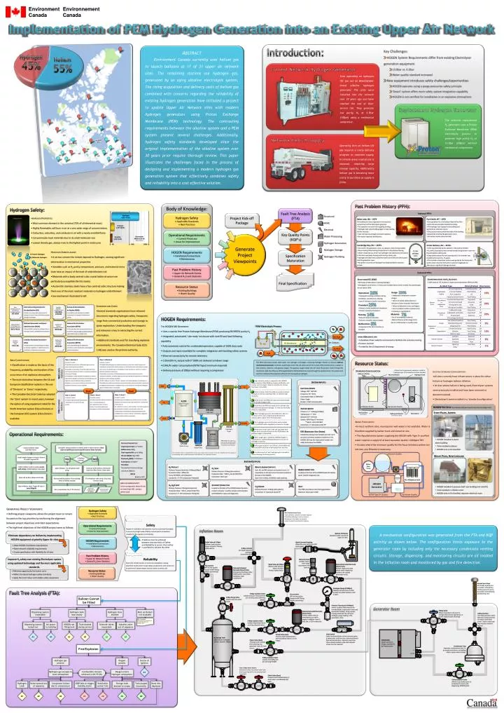
Environment Environnement Canada Canada H2O H2 A200 Water/Oxygen Separator O2 EM100 PEM Stack H2O H2O+H2 X334 Hydrogen Dryer + Standard for Gaseous Hydrogen Systems NFPA 50A Standard for Classifying Hazardous Locations NFPA 497 Canadian Hydrogen Installation Code CAN/BNQ 1784-000 Safety Standard for Hydrogen and Hydrogen Systems NSS 1740.16 Basic Considerations for the Safety of Hydrogen Systems ISO 15916 Canadian ElectricalCode C22-1-06 A300 Water/ Hydrogen Separator 50% 100% 0% O2 H2 CP205 Water Pump GB208 Water Filter + H2 H2 +H2O NEC (USA) Definition Implementation of PEM Hydrogen Generation into an Existing Upper Air Network H2 Gas @100psi T<0°C Abstract Environment Canada currently uses helium gas to launch balloons at 17 of 31 upper air network sites. The remaining stations use hydrogen gas, generated by an aging alkaline electrolysis system. The rising acquisition and delivery costs of helium gas combined with concerns regarding the reliability of existing hydrogen generation have initiated a project to update Upper Air Network sites with modern hydrogen generators using Proton Exchange Membrane (PEM) technology. The contrasting requirements between the alkaline system and a PEM system present several challenges. Additionally, hydrogen safety standards developed since the original implementation of the alkaline system over 30 years prior require thorough review. This paper illustrates the challenges faced in the process of designing and implementing a modern hydrogen gas generation system that effectively combines safety and reliability into a cost effective solution. Class 1, Division 1 A location in which: (1) Ignitable concentrations of flammable gases can exist under normal operating conditions. (2) Ignitable concentrations of such flammable gases may exist frequently because of repair or maintenance operations or because of leakage. (3) Breakdown or faulty operation of equipment or process might release ignitable concentrations of flammable gas and might also cause simultaneous failure of electrical equipment in such a way as to directly cause the electrical equipment to become a source of ignition. Class 1, Division 2 A location in which: (1) Volatile flammable gases are handled, processed, or used, but in which the gases will normally be confined within closed containers or closed systems from which they can escape only in case of accidental rupture or breakdown of such containers or systems or in case of abnormal operation of equipment. (2) Ignitable concentrations of flammable gases are normally prevented by positive mechanical ventilation, and which might only be come hazardous through failure or abnormal operations of the ventilating equipment. (3) That is adjacent to a Class 1 Division 1 location, and to which ignitable concentrations of flammable gases might occasionally be communicated unless such contamination is prevented by adequate positive-pressure ventilation from a source of clean air and effective safeguards against ventilation failure are provided. Water CSA (Canada) Definition PEM Electrolysis Process - - - H2+H2O Equal Equal - Class 1, Zone 0 A location in which: (1) Explosive gas atmospheres are present continuously or are present for long periods Class 1, Zone 1 A location in which: (i) Explosive gas atmospheres are likely to occur in normal operation; or (ii) Is adjacent to a Class 1, Zone 0 location, from which explosive gas atmospheres could be communicated. Class 1, Zone 2 A location in which: (i) Explosive gas atmospheres are not likely to occur in normal operation and, if they do occur, they will exist for a short period of time only; or (ii) Is adjacent to a Class 1, Zone 1 location, from which explosive gas atmospheres could be communicated, unless such communication is prevented by adequate positive-pressure ventilation from a source of clean air, and effective safeguards against ventilation failure are provided. - - - - - - Catalyst PE Membrane - + + + Introduction: • Key Challenges: • HOGEN System Requirements differ from existing Electrolyser generation equipment • 13.8bar vs. 6.9bar • Water quality standard increased • New equipment introduces safety challenges/opportunities • HOGEN operates using a purge-pressurize safety principle • ‘Smart’ system offers more safety system integration capability • HOGEN is not certified for installation in an explosive atmosphere + - - - + + + + O2+H2O - - - - - - H2O Sites operating on hydrogen lift gas use an Electrolyser brand alkaline hydrogen generator. The units were installed into the network over 30 years ago and have reached the end of their service life. They generate low purity H2 at 6.9bar (100psi) using a mechanical compressor. Current Network Hydrogen Generator Hydrogen 45% The selected replacement H2 generator uses a Proton Exchange Membrane (PEM) electrolysis process to generate high purity H2 at 13.8bar (200psi) without mechanical compression. Helium 55% Replacement Hydrogen Generator Operating sites on helium lift gas requires a costly delivery program to maintain supply. In remote areas road access is seasonal, requiring large storage capacity. Additionally helium gas is becoming more costly to purchase as supply is finite. Network Helium Supply Past Problem History (PPH): Hydrogen Safety: Internal PPH: Hydrogen 4.0%~75.0% • Hydrogen Properties: • Most common element in the universe (75% of all elemental mass) • Highly flammable, will burn in air at a very wide range of concentrations • Colourless, odourless, and combusts in air with a nearly invisible flame • Can permeate most materials due to its small molecular size • Lowest density gas, always rises to the highest point in enclosures • Baker Lake, NU – 1979 • Fire believed to have originated in the electrical compartment of the Electrolyser generator. • Fire spread to structure fully engulfing building. • Hydrogen tank inside building began to leak, feeding the fire intensity. • Leak rate was low enough to prevent explosion • No injuries reported, building lost. • Fort Smith, NT – 1979 • During balloon fill, a full balloon lifted off the filler nozzle and was propelled toward the ceiling. • The hydrogen was trapped in the building and ignited by an unknown source. • The pressure wave pushed the walls of the building outward also entering the generation room.. • No serious injuries were reported. Hydrogen Flame Propane 1.7%~10.9% Flammable Mixtures in Air (% by volume) Gasoline 1.0%~6.0% • Cambridge Bay, NU – 1970’s • Occurred in the generation room, no operator onsite during incident • Room heating failed causing temperatures to drop below freezing • Water condensed out of the ‘wet hydrogen’ and collected at the bottom of the tank, eventually freezing and bursting a drain pipe • Hydrogen at 6.9bar then pushed the water out of the tank and escaped into the generation room. • No ignition occurred and hydrogen had dispersed before operator arrived. • Corral Harbour, NU – 1970’s • A fire was detected by the operator in the wall vent heater. • O2 and H2 by-products were vented outside the generator room into the atmosphere side by side. • Deep snow covered the vent opening and a ‘ice chamber’ was created by the warm O2 - H2 gases. • The chamber of explosive mixture was ignited by the thermostat switch used to heat the vent ports to prevent clogging by ice. • No injury or significant damage occurred. • Hydrogen Embrittlement: • A serious concern for metals exposed to Hydrogen, causing significant deterioration in mechanical properties • Variables such as H2 purity, temperature, pressure, and material stress state have an impact of the level of embrittlement risk • Materials with a body centred cubic crystal lattice structure are particularly susceptible (ferritic steels) • Austentitic stainless steels have a face centred cubic structure making them one of the most resistant materials to hydrogen embrittlement • See mechanism illustrated to left Hydrogen Embrittlement Damage External PPH: Body of Knowledge: Countermeasures for H2 Accidents A 2005 study of 175 incidents in Japan occurring between 1949 and 2002. • Study from ISO 15916 • 1974 study of 96 incidents involving hydrogen. • Investigated causal factors, in many cases multiple factors were involved, thus percentages do not add to 100%. Fault Tree Analysis (FTA) • Structural • HVAC • Electrical • Water Processing • Hydrogen Generation • Hydrogen Storage • Hydrogen Plumbing Project Kick-off Package Hydrogen Safety • Applicable Standards • Best Practices 25% 26% • Design • Inadequate component or system designs • Failure to specify safety devices or omission of other essential information • Failure to determine stress and fatigue. • Error in material notation (clerical error in drawing or specification) • Operational • Inadequate working conditions during installation, maintenance, cleaning. • Lack of training or specific instructions Key Quality Points (KQP’s) Operational Requirements • Current Processes • Areas for Improvement Generate Project Viewpoints 25% • Standards and Codes: • Several standards organizations have released documents regarding hydrogen safety. Viewpoints range from commercial production and storage to space exploration. Understanding the viewpoint and relevance is key to extracting the correct information. • Additional standards exist for classifying explosive environments. The Canadian Electrical Code (C22-1-06) was used as the primary authority. • Procedural • Failure to follow established procedures • Failure to prepare procedures H+ Atomic Hydrogen + H2 Molecular Hydrogen 7% 14% HOGEN Requirements • Installation/Connections • Maintenance • Planning • Failure to prepare test plans • Failure to complete hazard studies • Materials • Use of incompatible materials • Material failures within design limits due to contamination or quality issues. Specification Maturation HOGEN Requirements: International Organization for Standardization (ISO) Considers the unique safety requirements of hydrogen systems. Created to facilitate emerging hydrogen technologies. Bureau de Normalization du Quebec (BNQ) An installation code developed to establish requirements for hydrogen infrastructure in Canada. + 8% + + • The HOGEN S40 Generator: • Uses a caustic free Proton Exchange Membrane (PEM) producing 99.9995% purity H2 • Integrated, automated, ‘site ready’ enclosure with tank fill and load following capability • Fully automatic control for unattended operation, capable of 100% duty cycle • Outputs and inputs available for complete integration with building safety systems • Ethernet connectivity for remote telemetry • 1.05m3/hr H2 output with 0~100% net delivery turndown range • 0.94L/hr water consumption (ASTM Type2 minimum required) • Delivery pressure of 200psi without requiring a compressor • Malfunctions • Components that fail to function as intended + - Past Problem History • Upper Air Network Events • General H2 Event Statistics - + + Final Specification • www.H2Incidents.org • A database driven website constructed to facilitate the voluntary sharing of lessons learned • Funded by the US department of energy National Aeronautics and Space Administration (NASA) Discusses NASA’s methods for hydrogen safety in their space, launch, and laboratory environments. National Fire Protection Association (NFPA) US fire code that covers the requirements for H2 gas systems. Does not apply to systems where H2 is generated on site, or storage <11m3 Resource Status • Existing Buildings • Water Quality Canadian Standards Association (CSA) A broad document covering all aspects of safety for electrical installations. In depth discussion of classification of hazardous environments. National Fire Protection Association (NFPA) US fire code illustrating the method and conventions used to classify areas containing and explosive atmosphere. • Area Classification: • Classification is made on the basis of the frequency, probability, and duration of the occurrence of an explosive atmosphere. • The main distinction between the US and European classification systems is the use of ‘Divisions’ or ‘Zones’ respectively. • The Canadian Electrical Code has adopted the ‘Zone’ system in recent years, however the option of using equipment rated for the North American system (Class-Division) or the European (IEC) system (Class-Zone) is available. The PEM Electrolysis process splits water into hydrogen and oxygen, producing hydrogen directly at pressure without mechanical compression. As shown, water (H2O), enters the cell and is split at the surface of the membrane by a catalyst to form protons, electrons. and gaseous oxygen. The gaseous oxygen leaves the cell while the protons move through the membrane under the influence of the applied electric field and electrons move through the external circuit. The protons and electrons combine at the opposite surface to form pure gaseous hydrogen. Resource Status: • Existing Standard Configuration: • All sites currently have infrastructure in place for either helium or hydrogen balloon inflation. • At sites where helium is being used, Electrolyser systems were previously installed and have been removed or decommissioned. • Electrolyser’s were installed in a ‘standard configuration’. Standard Configuration All electrical components explosion rated for hydrogen gas. All conductive surfaces bonded. Balloon Inflation Table Reserve Helium Hydrogen Tank Inflation Room Generator Room System Inputs: Electrical Power Voltage: 205 ~ 240 VAC Frequency: 50 ~ 60 Hz Consumption Rate: 6.7kWh/Nm3 Phase: Single Breaker: 12kVA recommended High resistivity water is supplied to the HOGEN under pressure (22psi MIN) by a water purification unit. A valve controls water intake to maintain the correct fluid level in the A200. 1 HOGEN Test Sites Two network sites were used as test sites for design trials Purified Water Pressure: 1.5 ~ 4.0barg (22-58psi) Temperature: 5 ~ 35°C Demand: 0.0 ~ 0.94 L/hr Quality: ASTM Type-2* minimum *Type-2+ recommended Connection: ¼” tube push-to-lock PP 1 6 Stony Plains, Alberta Roll-up Door (both sides) Electrolyser Hydrogen Detector (mounted to ceiling) Water is drawn from the A200 via a pump and sent through an internal ‘polishing’ filter to maintain high resistivity. 8 • Water Purification: • In most northern sites, municipal or well water is not available. Water is therefore supplied by tanker truck and stored on site. • The AquaSolutions system supplying the HOGEN with Type 2+ purified water requires a supply of at least tap water quality <1000ppmTDS • In cases where the minimum quality for the Aqua-Solutions system are not met, pre-filtration is necessary. 2 7 ESD (Emergency Shut Down) Initiated by closing circuit between pin 6 & 7 on 9-pin serial connector located on back the of the HOGEN. ESD trips the input power breaker and safely shuts down the HOGEN Operational Requirements: Water enters the PEM cell stack and is electrolysed on the anode (oxygen) side. 3 • HOGEN installed in stand alone building • Tank installed outdoors • HOGEN area is EX classified 9 3 4 Water exits the PEM cell stack on the cathode side saturated with gaseous hydrogen. It is fed into the A300 where it is separated. 4 10 2 5 Pre-Filtration Unit Unknown Quality Known Parameters: Target ascent rate: 4.2~5.4m/s Balloon mass: 800g Total required lift: up to 2000g Fill rate (MAX): 15g/s (lift) Reserve H2 (MIN): 2.5 balloons H2 buoyancy: 1120g/m3 Therefore: The required minimum storage volume at 200psi is: 362.6L Based on NTP Mount Pearl, Newfoundland ‘Wet’ hydrogen gas exits the A300 and is fed into the dryer which uses a regenerating desiccant to remove water vapour from the product gas. HOGEN Generator 5 Inspect inflation table and filler frame. During fill, observe balloon to detect holes or deformations. Close valve at half-fill point and enter fill room to listen for leaks. System Outputs: *Not shown: The A300 has a drain circuit that feeds water back behind the A200 where it is picked up by the pump. Water from Truck H2 Product Delivery Pressure (Nominal): 13.8barg (200psi) Production Rate: 1.05Nm3/hr Purity: 99.9995%, -65°C Dewpoint Connection: ¼” CPI Compression Fitting (SS) O2 Vent Delivery Pressure: 0.0barg (atmospheric) Production Rate: ~50% H2 rate (0.53Nm3/hr) Connection: Open port Remote Alarm Contacts Com, NC, and NO contacts are located on pins 1-3 respectively on the 9-pin serial connector located on the back of the HOGEN. Type: Form C Relay, 2A/30VDC rated switching RS232 Connection Located on the front of the HOGEN beside the display panel. Used for diagnostic tool Install weight hanger to nozzle. Amount to match required lift. Is balloon leaking? ‘Dry’ hydrogen gas exits the dryer and is output from the HOGEN under regulated pressure for storage. 6 NO YES The schematic shown is representative of the actual system layout, however it has been simplified for the purpose of understanding. Refer to HOGEN drawing XP-2001-0364 rev.T for a detailed schematic. ASTM Type 2+ Quality Tap Water Quality Attach balloon neck to nozzle, secure with clamp. Unfold balloon onto table Continue to fill balloon until nozzle rises from filler frame. Close valve. Abort inflation. Tie off balloon with string. Water exits anode side of the cell saturated with oxygen and is circulated back into the A200 where the gaseous oxygen is separated. H2-H2O Vent Delivery Pressure: 0.0barg (atmospheric) Production Rate: ~10% H2 rate (0.11Nm3/hr) Connection: ½” CPI Compression Fitting (SS) Ethernet Connection Located on the back of the HOGEN beside the alarm contact connector. Used for remote communication with HOGEN for status and diagnostics. H2O Drain Delivery Pressure: 0.0barg (atmospheric) Connection: ¼” tube push-to-lock PP Heat The PEM cell produces heat during generation. Maximum Heat Load: 4.3kW 7 • HOGEN installed in purpose built new building (not retrofit) • Tank installed in inflation room • HOGEN area is EX classified, separate electrical room Open roll up door (down wind side). Remove leaking balloon from building. Allow to deflate outside. Tie off balloon with string. Once tied, remove clamp. Area for Improvement: Current configuration allows fill rate to exceed 15g/s (lift) , posing a safety hazard ‘Wet’ oxygen gas is vented by HOGEN. Oxygen is inspected by a combustible gas detector to ensure no hydrogen is present. 8 Open inflation valve. Target fill rate is: 1min/100g-lift Get a new balloon for 2nd fill attempt. Record lift reading and tie off balloon. Record hydrogen tank pressure. • Generating Project Viewpoints: • Defining project viewpoints allows the project team to remain focused on the top priorities by reinforcing the alignment between project objectives and client expectations. • The high level objectives of the HOGEN project were as follows: Hydrogen Safety • Applicable Standards • Best Practices If the water quality is not sufficient, the HOGEN will drain the A200 and draw a new supply from the inlet. 9 Non-Heated Vent Stack Tank contents contain no water vapour. Therefore freezing is not a concern. Measures to be taken to prevent water/contaminant/animal ingress Viewpoint 1: Safety Aspects of installation and operation must be scrutinized thoroughly to ensure any single mode of failure cannot lead to a hazardous situation for the operator or the facility. Operational Requirements • Current Processes • Areas for Improvement A small amount of ‘wet’ hydrogen gas is vented for disposal during the drying process. 10 A mechanical configuration was generated from the FTA and KQP activity as shown below. The configuration limits exposure to the generator room by including only the necessary condensate venting circuits. Storage, dispensing, and monitoring circuits are all located in the inflation room and monitored by gas and fire detection. Inflation Room Eliminate dependency on Helium by implementing HOGEN equipment at priority Upper Air sites. Balloon Fill Nozzle Standard nozzle used at all upper air sites. HOGEN Requirements • Installation/Connections • Maintenance A balance must be achieved between characteristics of Safety and Reliability to ensure that neither is sacrificed to achieve the other • Meet HOGEN installation requirements • Meet network reliability requirements • Create specification with flexibility for all sites Quick Connect Coupling Allows for easy switching of fill hose supply. Relief Valve @ 250psi Relieves tank pressure above set point. Primary safety device. 4-Way Junction Use larger diameter tubing for unrestricted flow Viewpoint 2: Reliability Due to the remote location of most sites, breakdown causing downtime would result in major delays to operations until service can be performed. System design must be robust as well as safe. Past Problem History • Upper Air Network Events • General H2 Event Statistics Improve H2 safety over existing Electrolyser system using updated technology and the most applicable standards. Metering Valve Set flow rate to meet 15g/s requirement and lock out. Relief Valve @ 250psi Relieves tank pressure above set point. Primary safety device. Solenoid Actuated Normally Closed Valve Remote dispensing valve allows entire dispensing system to be outside generation room. Tee Junction NPT at one end for Swage-to-NPT fitting (allows positioning) • Minimize opportunity for human error • Reflect the latest hydrogen safety standards • Apply the most robust and reliable safety equipment Solenoid Actuated Normally Closed Valve Emergency Discharge Valve (EDD) used in case of fire. (voluntary code compliance) Resource Status • Existing Buildings • Water Quality Heated Vent Stack Electrically heated vent to outdoor atmosphere. Heating prevents wet H2 by-product from freezing and blocking vent. Analogue Gauge (0-300psi) Displays tank pressure at tank location provided isolation valve is open. Fire/Explosion Fault Tree Analysis (FTA): 2-Way Isolation Valve Isolates pressure measurement for servicing and confirming gauges Tee Junction NPT at one end for Swage-to-NPT fitting (allows positioning) 2-Way Purge Valve Used as vent for water purge Hydrogen gas present Oxygen present Source of ignition Pressure Transducer (0-300psi) Sensor to detect tank pressure for remote display in generator room and operations building. Using remote sensing eliminates the risk of an analogue gauge leaking in the generation room. Generator Room 3-Way Valve Allows H2 product to be sent to storage tank (normal operation), or to vent stack (trouble shooting) Solenoid Actuated Normally Closed Valve Primary safety valve to immediately turn off H2 supply to inflation room if leak, fire, or ESD is detected. A1 4-Way Junction Use 4-way junction rather than two 3-way junctions to reduce connection points. Vent to stack and trap must be oriented vertical. Hydrogen gas escapes to local atmosphere Combustible mixture achieved (4.0%-75.0%) Oxygen enters Hydrogen atmosphere 2-Way Isolation Valve Isolates dispensing line for servicing solenoid valves. Hydrogen Leak Valve opened out of sequence Component failure due to overpressure CGD fails to trigger building alarm Ventilation system fails Storage tank drained to empty Tank purged incorrectly Burst disc deployed Flow Switch Switch to detect failure of the solenoid valves. If valves leak, or fail to close, switch will detect flow and sound alarm. Operator must then close manual isolation valve and solenoid valves must be repaired. Check Valve (5psi) Prevents tank contamination from back flow if tank is run to empty. B1 B2 B3 C1 C2 D1 D2 H2 Storage Tank Approved for hydrogen service, rated for 300psi. Check Valve (5psi) Prevents tank contents from draining into generator room if a leak occurs. HOGEN S40 Shown are the H2 Product and Wet H2 By-Product ports. Condensate Trap Separates condensation from H2 by product and drains to building drain or gray water storage. Balloon Cannot be Filled 2-Way Isolation Valve Isolates tank filling line for servicing HOGEN Dispensing system inoperable Hydrogen tank near empty Hydrogen lines blocked Back up Helium not available Two 2-Way Drain Valves Redundant valve to prevent valve leak from requiring tank to be emptied and re-purged. Check Valve (5psi) Prevents tank contamination if drain valve is accidentally left open. KQP- Procedure: Back up helium quantities to be sized based on site isolation level. 2-Way Isolation Valve Allows H2 by product port to be blocked to assist with diagnosing HOGEN faults. Dispensing system locked-out No power to building HOGEN not filling tank Tank drained during service Solenoid valves inoperable Isolation valve out of sequence A1 A2 B1 B2 C1 C2