Download
1 / 17
170 likes | 365 Vues
TES Bolometer Array. For the APEX-SZ Camera. Jared Mehl University of California, Berkeley LTD 12, Paris, 2007. Collaborators. U. C. Berkeley Bill Holzapfel Zigmund Kermish Adrian Lee Martin Lueker Jared Mehl Tom Plagge Paul Richards Dan Schwan Martin White. McGill University

E N D
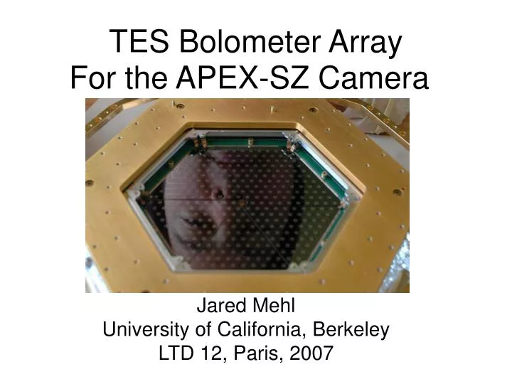
TES Bolometer Array For the APEX-SZ Camera Jared Mehl University of California, Berkeley LTD 12, Paris, 2007
Collaborators U. C. Berkeley Bill Holzapfel Zigmund Kermish Adrian Lee Martin Lueker Jared Mehl Tom Plagge Paul Richards Dan Schwan Martin White McGill University Matt Dobbs Trevor Lanting James Kennedy MPIfR Rolf Guesten Ruediger Kneissl Ernst Kreysa Karl Menten Dirk Muders Peter Schilke Axel Weiss University of Colorado Nils Halverson Dan Becker Amy Bender University of Bonn Kaustuv Basu Frank Bertoldi Martin Nord Florian Pacaud Cardiff University Peter Ade LBNL Helmuth Spieler MPE Hans Boehringer NIST Hsiao-Mei Cho
APEX-SZ • 12 m antenna, ALMA prototype • 5100 m Atacama Plateau, Chile • 320 element TES bolometer array • Frequency domain SQUID • multiplexer readout • Pulse-Tube Cooler (PTC) • Use Sunyaev-Zel’dovich effect to • study galaxy clusters • Operating and taking data
TES Array • Horn-coupled • 55 Pixels Per Wedge • 6 Wedges Per Array
TES Array • Horn-coupled • 55 Pixels Per Wedge • 6 Wedges Per Array
R ~ 1.2 normal T ~ 450 mK C t ~ 9 ms optical TES Bolometer • Au spiderweb absorber R ~ 200 / sq • Al/Ti Bilayer TES • Au Thermal Link G ~ 200 pW / K • low-stress Si N substrate, released with XeF etch 3 4 2
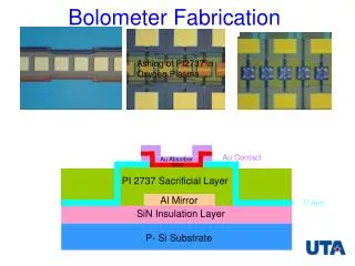
Bolometer Cavity Design Band-defining filters Waveguide Feed Horn Spiderweb Absorber TES Silicon Wafer Airgap Invar Backshort
Bolometer Cavity Simulation 150 GHz Simulation, 200 Ohm/sq Abs, λ/4 Backshort Absorbed Power Reflected Power Radiated Power • Optimize bolometer cavity • HFSS - Ansoft Corporation - 3D finite-element electromagnetic sims
Frequency Domain Multiplexer AC bias bolometers from 200 kHz – 1 MHz
Frequency Domain Multiplexer AC bias bolometers from 200 kHz – 1 MHz • Zero power dissipation • at sub-Kelvin stage • Strong rejection of time- • varying B-fields • Simple shielding • requirements • Reduced vibration • sensitivity
Frequency Domain Multiplexer SQUID array made by NIST
Bolometer Stability t sensor 5.8 Conservative Stability Criterion: > [ Irwin, JAP,1998 ] t bias For current fMUX (AC bias) at 50% bolometer superconducting transition: 2L t MUX = ~ 50 μs bias R Too fast for stable operation Early bolometers: C t = ~ 100 μs 0 G With conservative stability criterion we can tolerate: t t = / (Loopgain + 1) > 300 μs 0 sensor
Increasing Heat Capacity Current Bolometers: • Add 3 μm thick gold ring • Slow down detectors t ~ 30 ms 0 • Allows operation deep into transition • Critical for heat capacity to be • strongly coupled to TES
120 aW / Hz 1/2 Noise Performance
Cluster Map Abell 2163 ~1 hour integration Courtesy T. Lanting
South Pole Telescope • Sub-millimeter Wavelength Telescope: • 10 meter telescope (1’ FWHM beam at 150 GHz) • 1st Generation Camera: • 1 sq. deg FOV • ~1000 pixels • Observe in 3+ bands between 95-220 GHz simultaneously with a modular focal plane 220 GHz 150 GHz 95 GHz 150 GHz 150 GHz Funded by NSF 95 GHz