Download
1 / 20
210 likes | 434 Vues
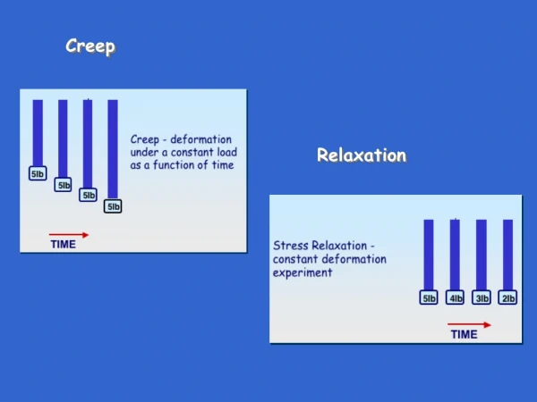
CREEP. It can be defined as the slow & progressive (increasingly continuing) deformation of a material with time under a constant stress. It is both a time & temperature dependent phenemenon.

E N D
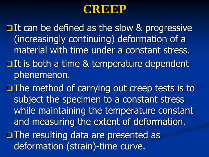
CREEP • It can be defined as the slow & progressive (increasingly continuing) deformation of a material with time under a constant stress. • It is both a time & temperature dependent phenemenon. • The method of carrying out creep tests is to subject the specimen to a constant stress while maintaining the temperature constant and measuring the extent of deformation. • The resulting data are presented as deformation (strain)-time curve.
Deformation (strain) E D V0 C B Instantaneous elastic strain A Time Tertiary Creep Secondary Steady-State Creep Primary Creep
When a load is applied at the beginning of a creep test, the instantaneous elastic deformation (AB) is followed by transient or primary creep (BC) then the secondary or steady-state creep (CD) and finally by tertiary or accelerated creep (DE). • Instantaneous deformations Elastic • The primary creep rate has a decreasing rate because of work hardening. It is similar to delayed elasticity (retarded elasticity) and the deformations are recoverable.
Secondary creep is essentially viscous in character. The minimum creep rate (V0) is determined by the slope Δε/Δt. The secondary creep stage is highly temperature-sensitive. It can be related to temperature with an equation similar to that in viscosity.
tr: time to failure a, n: material constants • Tertiary creep occurs at an accelerated rate. Time to rupture & stress relationship can be given as: • The two parameters determined from creep tests are: • Δε/Δt(Steady state creep rate): engineering design parameter for long-life applications. • Rupture lifetime (tr): relatively short-life applications
Creep Strain T4 or σ4 T3 or σ3 T2 or σ2 T1 or σ1 Time T1<T2<T3<T4 σ1<σ2<σ3<σ4 • Both temperature & applied stress adversely affect the creep strains. Usually under the same temperature different stress levels are applied & the creep strains are determined.
Creep Strain σ3=69MPa σ2=62MPa dε/dt dε/dt σ1=55MPa dε/dt Time • When the slope of two curves (dε/dt) are determined the material constants can then be determined. In practice, however, three or more stress levels are usually used for discrepancies in lab data.
Creep Strain For 55 MPa → 62 MPa 0.0066 1/hr For 62 MPa → 55 MPa 0.0025 1/hr Time (hrs) Ex: In the creep test of an aluminum alloy at 180°C various stresses were applied and the corresponding creep rates were determined. Determine the creep rate for the stress of 59 MPa
n = 8.1 So for σ = 59 MPa 1/hr
FATIQUE • Under fluctuating / cyclic stresses, failure can occur at loads considerably lower than tensile or yield strengths of material under a static load: Fatigue • Estimated to causes 90% of all failures of metallic structures (bridges, aircraft, machine components, etc.) • Fatigue failure is brittle-like (relatively little plastic deformation) - even in normally ductile materials. Thus sudden and catastrophic! • Applied stresses causing fatigue may be axial (tension or compression), flexural (bending) or torsional (twisting). • Fatigue failure proceeds in three distinct stages: crack initiation in the areas of stress concentration (near stress raisers), incremental crack propagation, final catastrophic failure.
σ Fluctuating stress Δσ σmean σmax σmin σmax Reversed stress Δσ σmean=0 time σmin Cyclic stresses are characterized by maximum, minimumand mean stress, the range of stress, and the stress ratio
Fracture caused by fatique is brittle (even in ductile materials) • Fatique Tests are carried out to determine: • The stresses that can be applied over a specified number of repetitions • The life under a specified stress level • For ferrous metals and alloys the strength of the material under repeated stress is called as “Endurance Limit” or “Fatique Limit” • For most other materials fatique limit does not exist. In those the strength under repeated loading is given by “Fatique Strength”
Fracture strength(S) Steel Fatique Limit Aluminum Fatique strength # of load repetition (log N) 1 10 100 103 106 • In a fatique test, stress-number of load repetitions is plotted to obtain S-N curves (Wohler Curves)
Endurance Limit: Maximum stressthat can be applied repeatedly an infinite number of times (for most steels 35%-60%) • Fatique Strength: Maximum stress that can be applied repeatedly over a specified number of load repetitions (for example 106) • The relationship b/w stress and number of load repetitions is given by: k: constant n: constant (8-15) σ: stress N: # of repetitions
Factors Affecting the Fatique Behavior • Quality • Environmental Conditions (temperature, corrosion) • Range of Stress • Frequency of Loading • Surface Effects (Most cracks start from the surface. Better design coulb be utilized to reduce this) Avoid sharp corners (poor) Round corners (better design)