Download

1 / 59
620 likes | 831 Vues
Evaluating Long Term CO 2 Storage in Saline Aquifers. Mary Fanett Wheeler Center for Subsurface Modeling The University of Texas at Austin. Acknowledge. Collaborators:

E N D
Evaluating Long Term CO2 Storage in Saline Aquifers Mary Fanett Wheeler Center for Subsurface Modeling The University of Texas at Austin
Acknowledge Collaborators: Algorithms: UT-Austin ( B. Ganis, G. Pencheva, G.. Xue, H. Florez, B. Wang, R. Tavakoli) ; Pitt (I. Yotov); Paris VI (V. Girault, M. Vohralik); Lyon (A. Mikelic) Parallel Computation: IBM (K. Jordan), Rutgers (M. Parashar) Phase Behaviour and Compositional Modeling : UT-Austin ( M. Delshad, X. Kong); Chevron (S. Thomas) Support of Projects: NSF, DOE (DE-FG02-04ER25617 and EFRC-DE-SC0001114), CSM Industrial Affiliates
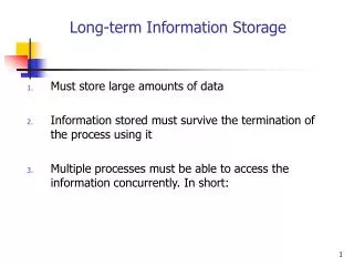
Outline Motivation Why Carbon Capture and Storage (CCS)? Mechanisms, Questions Needing Answers Mathematical and Computational Models Benchmarks Investigate applicability of existing oil/water/gas models to supercritical C02/water strategy Calibrate and history match demonstration sites Mathematical and Computational Challenges Discretizations and Solvers Multiscale, Multiphysics, Multinumerics & Data Assimilation Conclusions
World Primary Energy Demand 18 000 Mtoe Other renewables 16 000 Hydro 14 000 Nuclear 12 000 Biomass 10 000 Gas 8 000 6 000 Coal 4 000 Oil 2 000 0 1980 1990 2000 2010 2020 2030 From: Joan MacNaughton (Alstom Power Company) World energy demand expands by 45% between now and 2030 – an average rate of increase of 1.6% per year – with coal accounting for more than a third of the overall rise
CO2 from Fossil Fuel Combustion 30 Total: 26,6 Gt in 2005 GtCO2 by sector 30 20 Others 16 % Transport Power by fuel 22 % World CO2 fossil emissions 20 Gton of CO2 Industry 22 % Oil 3 % 10 Gas 8 % 41 % Power 10 Coal 70 % 0 1 Source: IEA/OECD (200) Units:1 Gt = 10^12 kg From: Joan MacNaughton (Alstom Power Company) 0 Year 1880 1900 1920 1940 1960 1980 2000 2020 Source: Alstom, adapted from CDIAC 2004 Coal generates 70% of the CO2 emissions from power generation
Center for Frontiers of Subsurface Energy SecurityThe University of Texas Summary statement: Our goal is scientific understanding of subsurface physical, chemical and biological processes from the very small scale to the very large scale so that we can predict the behavior of CO2 and other byproducts of energy production that may need to be stored in the subsurface. • RESEARCH PLAN AND DIRECTIONS • Challenges and approaches: Integrate and expand our knowledge of subsurface phenomena across scientific disciplines using both experimental and modeling approaches to better understand and quantify behavior far from equilibrium. • Unique aspects: The uncertainty and complexity of fluids in geologic media from the molecular scale to the basin scale. • Outcome: Predict long term behavior of subsurface storage.
Multi-Scale Investigation SC-CO2 Dissolved CO2 Aquifer Brine
Gulf Coast Stacked Storage Project(SECARB) Geographical location of Denbury Resources, Incorporated’s Cranfield Unit east of Natchez, Mississippi
Research Questions ? How does supercritical CO2 behave in the subsurface? What are the relevant physics, biology, and chemistry of CO2 transport in the subsurface? Can we engineer solutions to mitigate contaminant leakage pathways? How can we represent the essential features of large-scale behavior that emerge from small-scale phenomena?
Goal of CO2 Geological Sequestration Injection Well Confining Layer(s) Supercritical CO2 Dissolved CO2 Precipitated Carbonate Minerals Permanently store CO2 in deep saline aquifers by different trapping mechanism: • Residual • Dissolution • Mineral • Structural Celia et al., 2002
Modeling CO2 Storage • Accurate prediction of the CO2 fate is a challenge • CO2 injection in subsurface brings a weighty list of variables, parameters, and potential outcomes • CO2 properties of density, viscosity, solubility depend on pressure, temperature, and water salinity • Relative permeabilities are functions of rock properties such as wettability and permeability • Relative permeability and capillary pressure are hysteretic • Relative permeability and capillary pressure are influenced by pressure, interfacial tension, and flow rate
Forces Controlling the Movement of CO2 • Pressure Gradient (Driving Force) • Buoyancy Force (Driving or Trapping Force) • Capillary Pressure (Trapping Force) Mobilization Condition of Trapped CO2Globule
Compositional Flow and Thermal Formulation
IPARS-COMP Flow Equations Mass Balance Equation Pressure Equation Solution Method Iteratively coupled until a volume balance convergence criterion is met or a maximum number of iterations exceeded.
Thermal & Chemistry Equations Energy Balance Solved using a time-split scheme (operator splitting) Higher-order Godunov for advection Fully implicit/explicit in time and Mixed FEM in space for thermal conduction Chemistry System of (non-linear) ODEs Solved using a higher order integration schemes such as Runge-Kutta methods
EOS Model Peng-Robinson EOS CO2 Properties Fugacity (T, P) Density (T, P) Viscosity (T, P) Aqueous Solution Properties CO2 Solubility (T, P) Aqueous Density (T, P) Effect of salinity
Subsurface Compositional Framework Gridding Parallel Solvers Geochemical Reaction EOSComp. Geomechanics Thermal 2 or 4- P Flash Visualization Physical Prop Numerics
EOS Compositional Flow Simulations6 Component Compositional BenchmarkLarge Scale CO2 SimulationCalibration: Resid. Sat & TrappingCore Studies and ScalingPreliminary – Matching Cranfield Field StudiesM. Delshad, X. Kong, and W
EOS Compositional Simulations After Three Years • Modified SPE5 WAG injection, 6 non-aqueous components-solved using EOS compositional model • SPE10 permeability distribution • 50x480x480 cells (~11 million) • Linear Solver: BiCGS or GMRES + MG preconditioner. Water Saturation Oil Pressure Gas Saturation Propane Concentration Permeability
Parallel Scalability Texas Advanced Computing Center The University of Texas at Austin
Large-Scale High Resolution Simulation--- 3.3 million cells CO2 saturation after 2 years Permeability, md CO2 Injection wells Vertical cross section Permeability and well locations
Residual Saturation vs. Trapping Number Points: data from Bennion and Bachu Line: Model
IPARS CorefloodSimulation • Generate heterogeneous permeability and porosity data with FFTSIM (geostatistics software) • Permeability and porosity are highly heterogeneous with a Dykstra-Parson coefficient of 0.6 • Honor average permeability and porosity of experimental data (Ref. SPE 126340) • Isotropic permeability Permeability in a cross section Permeability along the core
Simulation Data • Set up simulation model with same parameters as the experiment (SPE 126340)
Relative Permeability andCapillary Pressure • Relative permeability and capillary pressure used in simulation • Core is initially saturated with 100% water, residual of both CO2 and water is assumed to be 0.2 Drainage capillary pressure Drainage relative permeability
Numerical Experiment • Total injection: 7 pore volumes • Fine mesh cylindrical case, required very small time steps • Coarse grids used for testing purpose Gas Saturation at 0.3 Pore Volume with Mesh (32x32x64)
Cube and Coarse GridComparison Cases • Cube and coarse grid was used to test sensitivity of simulation to model parameters. • Grid : 8x8x32 Permeability for coarse case Porosity for coarse case
Case 1… Without PcScaling • CO2 narrowly distributed and uniform
Case 2… With PcScaling UsingJ-Leverret • CO2 histogram shows log normal distribution
Summary • For case without J-Leverret capillary pressure, CO2 saturation is more uniform and continuously distributed than that of experiment‘ • Locally non-uniform distribution of CO2 is shown in Case 2 • Final gas saturation with Pc scaling is close to experimental results of 0.54 (ref. Paper 126340). • Results indicate that J-Leverretfunction based capillary pressure is important for core flood simulation.
MFMFE for General Hexahededra and Simplices Formulation: W, Xue and Yotov Solvers: Siefert, Tuminaro (Sandia), Pencheva (UT Austin - EFRC)
Frio BrinePilot Site • Injection interval: 24-m-thick, mineralogically complex fluvial sandstone, porosity 24%, Permeability 2.5 D • Unusually homogeneous • Steeply dipping 16 degrees • 7m perforated zone • Seals numerous thick shales, small fault block • Depth 1,500 m • Brine-rock, no hydrocarbons • 150 bar, 53 C, supercritical CO2 Injection interval Oil production From Ian Duncan
Corner Point Grid for Frio Pilot Test Permeability
Multipoint Flux Mixed Finite Element BDM1 Space on reference element:
Multipoint Flux Mixed Finite Element(MFMFE) on General Hexahedra
Solver Performances for SPE 10Benchmark Problems • SPE 10 permeability on 220 x 65 x 50 highly • perturbed hexahedral mesh • Model 1: Symmetric multipoint flux • Model 2: Non-symmetric multipoint flux AMG solvers: HYPRE (developed by researchers at LLNL) SAMG (developed by the group of K. Stüben) FASP (developed by the group of J. Xu from Penn State) ML in Trilinos (developed by researchers at Sandia) (tested in a different code) Stopping criteria: relative residual less than 10-9. ML21 - 28 ML23 - 29
Parallel Non-Overlapping DD for MFMFE Using ML (Trilinos) • Smoothed Aggregation (SA) with standard SA dropping • Symmetric Gauss-Seidel for pre- and post-smoother within the W cycle • Drop tolerance discourages aggregates that traverse large material jumps • - give a sense for both total storage and total • cost per iteration • Increasing the drop tolerance tends to reduce iterations but increases complexity
Parallel EnKF for Reservoir History Matching G. Pencheva, R. Tavakoli, W, K. Jordan, M. Parashar
Continuous Measurement and Data Analysis for Reservoir Model Estimation Source: E. Gildin, CSM, UT-Austin
Recent Award • 1st Place, IEEE SCALE 2011 Challenge, “A Scalable Ensemble-based Oil-Reservoir Simulations using Blue Gene/P-as-a-Service”, with Rutgers and IBM.
Ensemble Kalman Filter (EnKF) • Monte Carlo approach for recursively updating the model parameters (as well as primary variables) based on an ensemble of prior realizations and observation data. • The EnKF consists of two steps: • Forecast step: running a set of reservoir simulations (IPARS) to predict data at the next update step • Update step: computing Kalman gain matrix and updating state vectors m True Model Production prediction t0 time t1 t2 t3
Serial vs. Parallel EnKF • Run Ne realizations simultaneously where each simulation run is performed in parallel • Sequentially run each of the realizations one after another for j=1, 2, …, Ne
Linear and Nonlinear Solvers • Reservoir simulation application uses models for multiphase flow in porous media: time-dependent, highly nonlinear, conserve mass. • We would like each realization to run efficiently (parallel scalable), so must utilize good solvers and preconditioners. • Moreover, need to synchronize multiple simulation runs during the EnKF process. (The update step is a barrier).
Solver with Preconditioning • In IPARS, linear system is solved using preconditioned generalized minimum residual (GMRES). • Two-stage preconditioning: • decoupling preconditioner stage: allows us to precondition the diagonal pressure block of the Jacobian independently of the saturation blocks • At the second stage, the pressure block is preconditioned
Dynamic Tolerance • In addition to proper choice of a preconditioner in solving a Jacobian equation (AX=B), the problem of an adequate tolerance in the linear solver appears. • The forcing term technique is used in IPARS to dynamically adjust the tolerance in the course of the Newton process (start with loose tolerance and tighten the condition as we proceed for further iterations) • The optimal choice of forcing factor has appeared to be 0.1 (FORCING=0.1)