Download
1 / 18
180 likes | 335 Vues
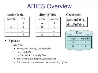
Overview of ARIES ACT-1 Study. Farrokh Najmabadi Professor of Electrical & Computer Engineering Director, Center for Energy Research UC San Diego and the ARIES Team Japan-US Workshop on Fusion Power Plants and Related Advanced Technologies with participations from China & Korea

E N D
Overview of ARIES ACT-1 Study Farrokh Najmabadi Professor of Electrical & Computer Engineering Director, Center for Energy Research UC San Diego and the ARIES Team Japan-US Workshop on Fusion Power Plants and Related Advanced Technologies with participations from China & Korea February 26-28, 2013
ARIES Program Participants Systems code: UC San Diego, PPPL Plasma Physics: PPPL , GA, LLNL Fusion Core Design & Analysis: UC San Diego, FNT Consulting Nuclear Analysis: UW-Madison Plasma Facing Components (Design & Analysis): UC San Diego, UW-Madison Plasma Facing Components (experiments): Georgia Tech Design Integration: UC San Diego, Boeing Safety: INEL Contact to Material Community: ORNL
Goals of ARIES ACT Study • Over a decade since last tokamak study : ARIES-1 (1990) through ARIES-AT(2000). • Substantial progress in understanding in many areas. • New issues have emerged: e.g., edge plasma physics, PMI, PFCs, and off-normal events. • What would be the maximum fluxes that can be handled by in-vessel components in a power plant? • What level of off-normal events are acceptable in a commercial power plant? • Evolving needs in the ITER and FNSF/Demo era: • Risk/benefit analysis among extrapolation and attractiveness. • Detailed component designs is necessary to understand R&D requirements.
Frame the “parameter space for attractive power plants” by considering the “four corners” of parameter space ACT-1 Reversed-shear (βN=0.04-0.06) DCLL blanket Reversed-shear (βN=0.04-0.06) SiCblanket ARIES-RS/AT SSTR-2 EU Model-D Higher power density Higher density Lower current-drive power Physics Extrapolation Decreasing P/R ACT-2 1st Stability (no-wall limit) DCLL blanket 1st Stability (no-wall limit) SiCblanket Lower power density Lower density Higher CD power ARIES-1 SSTR Engineering performance (efficiency) Lower thermal efficiency Higher Fusion/plasma power Higher P/R Metallic first wall/blanket Higher thermal efficiency Lower fusion/plasma power Lower P/R Composite first wall/blanket
Status of the ARIES ACT Study • Project Goals: • Detailed design of advanced physics, SiC blanket ACT-1 (ARIES-AT update). • Detailed design of ACT-2 (conservative physics, DCLL blanket). • System-level definitions for ACT-3 & ACT-4. • ACT-1 research is completed. • First design iteration was completed for a 5.5 m Device. • Updated design point at R = 6.25 m (detailed design on-going) • Final report to be published as a special issue of Fusion Science & Technology • ACT-2 Research will be completed by December2013.
ARIES-ACT1 (ARIES-AT update) • Advance tokamak mode • Blanket: SiC structure & LiPb Coolant/breeder (to achieve a high efficiency)
ARIES Systems Code – a new approach to finding operating points Example: Data base of operating points with fbs ≤ 0.90, 0.85 ≤ fGW ≤ 1.0, H98 ≤ 1.75 • Systems codes find a single operating point through a minimization of a figure of merit with certain constraints • Very difficult to see sensitivity to assumptions. • Our new approach to systems analysis is based on surveying the design space and finding a large number of viable operating points. • A GUI is developed to visualize the data. It can impose additional constraints to explore sensitivities
Impact of the Divertor Heat load • Divertor design can handle > 10 MW/m2 peak load. • UEDGE simulations (LLNL) showed detached divertor solution to reach high radiated powers in the divertor slot and a low peak heat flux on the divertor (~5MW/m2 peak). • Leads to ARIES-AT-size device at R=5.5m. • Control & sustaining a detached divertor? • Using Fundamenski SOL estimates and 90% radiation in SOL+divertor leads to a 6.25-m device with only 4 mills cost penalty (current reference point). • Device size is set by the divertor heat flux
The new systems approach underlines robustness of the design point to physics achievements * Includes fast a contribution of ~ 1%
The new systems approach underlines robustness of the design point to physics achievements * Includes fast a contribution of ~ 1%
Detailed Physics analysis has been performed using the latest tools * Discussed in the paper by M. Tillack, C. Kessel New physics modeling • Energy transport assessment: what is required and model predictions • Pedestal treatment • Time-dependent free boundary simulations of formation and operating point • Edge plasma simulation (consistent divertor/edge, detachment, etc) • Divertor/FW heat loading from experimental tokamaks for transient and off-normal* • Disruption simulations* • Fast particle MHD
Overview of engineering design: 1. High-hest flux components* * Discussed in paper by M. Tillack and J. Blanchard, • Design of first wall and divertor options • High-performance He-cooled W-alloy divertor, external transition to steel • Robust FW concept (embedded W pins) • Analysis of first wall and divertor options • Birth-to-death modeling • Yield, creep, fracture mechanics • Failure modes • Helium heat transfer experiments • ELM and disruption loading responses • Thermal, mechanical, EM & ferromagnetic
Overview of engineering design*: 2. Fusion Core * Discussed in the paper by M. Tillack, this session • Features similar to ARIES-AT • PbLi self-cooled SiC/SiC breeding blanket with simple double-pipe construction • Brayton cycle with h~58% • Many new features and improvements • He-cooled ferritic steel structural ring/shield • Detailed flow paths and manifolding for PbLi to reduce 3D MHD effects* • Elimination of water from the vacuum vessel, separation of vessel and shield • Identification of new material for the vacuum vessel
Detailed safety analysis has highlighted impact of tritium absorption and transport • Detailed safety modeling of ARIES-AT (Petti et al) and ARIES-CS (Merrill et al, FS&T, 54, 2008 ) have shown a paradigm shift in safety issues: • Use of low-activation material and care design has limited temperature excursions and mobilization of radioactivity during accidents. Rather off-site dose is dominated by tritium. • For ARIES-CS worst-case accident, tritium release dose is 8.5 mSv (no-evacuation limit is 10 mSV) • Major implications for material and component R&D: • Need to minimize tritium inventory (control of breeding, absorption and inventory in different material) • Design implications: material choices, in-vessel components, vacuum vessel, etc.
Revisiting ARIES-AT vacuum vessel • AREIS-AT had a thick vacuum vessel (40 cm thick) with WC and water to help in shielding. (adoption of ITER vacuum vessel). • Expensive and massive vacuum vessel. • ITER Components are “hung” from the vacuum vessel. ARIES sectors are self supporting (different loads). • ARIES-AT vacuum vessel operated at 50oC • material? • Tritium absorption? • Tritium transfer to water? • Vacuum vessel temperature exceeded 100oC during an accident after a few hours (steam!)
New Vacuum Vessel Design • Contains no water • Can run at high temperature: 300-500oC. (350 oC operating temperature to minimize tritium inventory) • Cooled by He flowing between ribs. • Tritium diffused through the inner wall is recovered from He coolant (Tritium diffusion to the cryostat and/or building should be much smaller. • Made of low-activation 3Cr-3WV baintic steel (no need for post-weld heat treatment).
In summary … • ARIES-ACT study is re-examining the tokamak power plant space to understand risk and trade-offs of higher physics and engineering performance with special emphais on PMI/PFC and off-normal events. • ARIES-ACT1 (updated ARIES-AT) is near completion. • Detailed physics analysis with modern computational tools are used. Many new physics issues are included. • The new system approach indicate a robust design window for this class of power plants. • Many engineering imporvements: He-cooled ferritic steel structural ring/shield, Detailed flow paths and manifolding to reduce 3D MHD effects, Identification of new material for the vacuum vessel … • In-elastic analysis of component including Birth-to-death modeling and fracture mechanics indicate a higher performance PFCs are possible. Many issues/properties for material development & optimization are identified.