Download
1 / 47
480 likes | 697 Vues
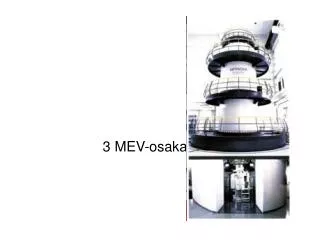
LINAC4 and 3 MeV test stand at CERN. Alessandra M. Lombardi G. Bellodi,M . Eshraqi,JB Lallement,S . Lanzone , E. Sargsyan. LINAC4 in the framework of CERN injectors LINAC4 beam dynamics : location of emittance growth, parameters for emittance control

E N D
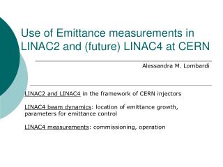
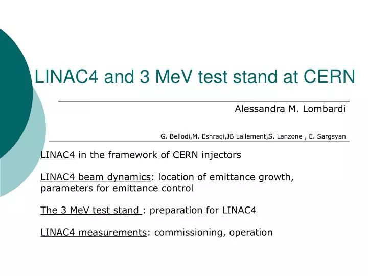
LINAC4 and 3 MeV test stand at CERN Alessandra M. Lombardi G. Bellodi,M. Eshraqi,JBLallement,S. Lanzone , E. Sargsyan LINAC4in the framework of CERN injectors LINAC4 beam dynamics: location of emittance growth, parameters for emittance control The 3 MeV test stand : preparation for LINAC4 LINAC4 measurements: commissioning, operation
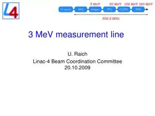
Linac4 Layout 45keV 3MeV 3MeV 50MeV 102MeV 160MeV H- RFQ CHOPPER DTL CCDTL PIMS Drift Tube Linac 352 MHz 18.7 m 3 tanks 5klystrons 4 MW 111 PMQuad Cell-Coupled Drift Tube Linac 352 MHz 25 m 21 tanks 7 klystrons 6.5 MW 21 EMQuads Pi-Mode Structure 352 MHz 22 m 12 tanks 8 klystrons ~12 MW 12 EMQuads RF volume source (DESY) 45 kV 1.9m LEBT Radio Frequency Quadrupole 352 MHz 3 m 1 Klystron 0.6 MW Chopper 352 MHz 3.6 m 11 EMquad 3 cavities Total Linac4: 80 m, 21klystrons Beam Duty cycle: 0.04% phase 1 (PSB) 0.08% phase 2 (LP-SPL) 3-4% phase 2 (SPL) (design for losses : 6%) 4 different structures, (RFQ, DTL, CCDTL, PIMS) Ion current: 40 mA (avg. in pulse), 65 mA (bunch)
Layout of the new injectors SPS PS2 ISOLDE PS SPL Linac4 LINAC4 to booster transfer line is 180 m long with two horizonthal bendings and one vertical
Linac4 Building Equipment building • Picture of the building • Picture of the the accelerator in the building Linac4 tunnel Linac4-Linac2 transfer line Low-energy injector Access building Vertical step (2.5 m) for compatibility with SPL
Beam Dynamics • generate an ideal layout assuming smooth phase advance, avoid resonances, implementing all the recipes for optimising beam quality • integrate engineering ,mechanical and cost considerations • generate a particle beam composed of 50 k to 500 k macroparticles • Track the motion of the macroparticles under the influence of space charge and electromagnetic fields with the programs PATH-PARMTEQM (CERN-LANL) and TRACEWIN-TOUTATIS (CEA). Independent check of results • Produce plots of global quantities (emittance, halo, ratio beam size-to-aperture) as well as detailed beam distribution at specified locations • On the basis of the results reiterate or validate a technical solution and/or mechanical layout • Perform statistical error studies to give tolerances (alignment , RF) and expected beam performance • Device measurements and commissioning scenarios (interface with DIAGNOSTICS)
LINAC end-to-end • emittancegrowth (30-40%) is located before 3 MeV • Bottlenecks : LEBT solenoids, chopper plates and chopped beam dump (wanted)
Losses Most of the losses occur before the beam has reached 3 MeV. Losses are mainly in the RFQ (5%) and the MEBT (7%). The total transmission is ~85%. LOSSES in the 3MeV MEBT
Beam transverse phase space LEBT in (45keV) RFQ in (45keV) RFQ out (3 MeV) DTL in (3MeV) CCDTL in (50MeV) PIMS in (100MeV) PIMS out (160MeV)
Emittance 0-3 MeV Symmetry x,y in LEBT, if source is symmetric Losses in the RFQ, emittance decreases Losses and emittance increase when matching to the DTL
Location and causes of e growth and losses • LEBT solenoids (divergent beam from the source). 45 keV • MEBT transport (abrupt change of phase advance). 3 MeV • BOTH ARE UNAVOIDABLE but they must be controlled
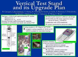
Testing the low energy part (0-3 MeV) : the 3 MeV test stand • Goals : • Validate by 2010 • Source and LEBT design • RFQ design • Chopper (by 2011) Source 45 keV Chopper Diagnostic line RFQ 3 MeV
Measurements at 45 keV (starting this year) • In steps • Source emittance • Source + solenoid emittance • Source + solenoid spectrometre
Measurements at 3 MeV (starting 09/2010) • Measurement program • Transport/setting up • Emittance • Halo developmnet • Without the dump • Chopping • With the dump
“chopping” removing microbunches (150/352) to adapt the 352MHz linac bunches to the 1 MHz booster frequency Match to the DTL Chop Match from the RFQ Emittance increase 20-30%
104 ions 1.15×10⁹ ions 2.84 ns Chopper line layout Matching section Matching section Chopping section for PSB : suppress 150/352 microbunches (1MHz) for SPL and Nufact : suppress 3/8 microbunches (40 MHz CERN nufact)
Diagnostics – permanent (ok for monitoring, not sufficient for setting up) Wire scanners Current transformers
Screen Chopper Diaphragm H- LEBT RFQ Chopper-line Possibility of making a pencil beam Reduced beam current from 70 to 4 mA Reduced beam size on the screen
Example : setting buncher phases 1/2 To be done with a pencil beam! 1. All bunchers off. It gives us a reference. 2. First buncher on. Setting the voltage and the phase. 3. Setting the Voltage and the phase of the second buncher. 4. Setting the Voltage and the phase of the third buncher.
Example : setting buncher phases 2/2 Scanning bunchers phase for different voltages allows us to cross-check buncher calibration and to set the buncher phases wrt the RFQ.
104 ions 1.15×10⁹ ions 2.84 ns Chopper LINAC4 for PSB : suppress 113/352 microbunches LINAC4 for SPL and Nufact : suppress 3/8 microbunches (40 MHz CERN nufact)
Example : validating the chopper 1/4 • Static measurements • Chopper on or off • Validate the chopper voltage and the optics (based on amplification by quad) • Time resolved measurements • Validate the rise and fall time of the chopper and its suitability for nufact p driver : 40 MHz and 50 Hz
Example : validating the chopper 2/4 • Test separately each component responsible for the chopping • Measurements to be done with a ‘pencil’ beam and without the dump in place Wire scanner B1 B2 B3 Q7 Q5 Q6 Q1 Q2 Q3 Q4 Q8 Q9 1.Only Chopper on : Q5, Q6, Q7 and B2 off. 2.Chopper and Q7 on : Q5, Q6 and B2 off. 3.Chopper Q5, Q6 and Q7 On : B2 off. 4.Chopper Q5, Q6, Q7 and B2 on.
Example : validating the chopper 3/4Static measurements Pencil beam All elements on Chooper on (top) Chopper off (bottom) With this we validate : • Chopper voltage • Optics we do not validate : • Space charge • Rise/fall time
Not completely chopped bunch Transmitted bunch Example : validating the chopper 4/4Time resolved measurements BSHM Measure residual H-in not completely chopped bunches with a sensitivity of ~ 104 ions, in the vicinity of full bunches ~ 109 ions. Time resolution and dynamic range tested with a laser
Commissioning and Operation of the Linac • Commissioning in step with dedicated measurement line • Installation in the tunnel of 3 MeV part • Installation of DTL tank1 – 10 MeV • Installation of DTL tank2 and 3 -50MeV • Installation of CCDTL – 100 MeV • Installation of PIMS – 160 MeV • Operation with minimum diagnostics • Lack of space
Focusing field “Locally” irregular due to extra space for intertank and diagnostic Can match current from 30 to 80 mA
Layout To be set/tuned (till BHZ40) : 2 solenoids, 75 quads 48 steerers settings 22 amplitudes and phases THERE ARE ABOUT 150 PARAMETERS TO SET
Movable Measurement Bench (commissioning only) Uli Raich AB/BI
Example-transverse plane 1) Matching to DTL : transmission at second transformer of the chopper line when changing the gradients of first 4 quadrupoles of the chopper line by 20% 2) DTL matching: Variation of quad b/w tank1 and tank2 with emittance measurement at end tank2 Variation of quad b/w tank2 and tank3 with emittance measurement at end DTL
Example- longitudinal plane DTL tank1 amplitude 1) Wide range, meas. with TOF 2) Few percent, meas. with spectro 4) Final setting, measure en spread 3) 1% percent, meas. with phase probe
Normalised transverse phase space Plot scale : 1cm X 2.5mrad CCDTL in (50MeV) PIMS in (100MeV) PIMS out (160MeV)
Challenges • The beam distribution is changing. The number of particles in one r.m.s. is changing. How to quantify emitt increase? • Space charge effects and coupling transverse- longitudinal influence the emittance : emittance depends on machine settings, emittance grows uncontrolled if the beam drifts for 10 X betalambda where βλ= 3.5 cm at 3 MeV ; 40 cm at 160 MeV We cannot use profiles to measure emitt • Alignment errors and gradient errors as budgeted should give an emittance increase with respect to nominal of 10% at 1 sigma • Transients, jitters : should be able to measure emittance of a slice of the beam in order to distinguish static errors from dynamics errors
Changing distribution PIMS output 160 MeV 50% of the beam in one rms RFQ input 45 keV 30% of the beam in one rms
Permanent Diagnostics • Minimal for lack of space • Phase probe after (almost) every klystron to be able to readjust phase and amplitudes • Position monitor wherever possible to adjust the steering (loss control) • Beam profile monitors at critical points, total of 11.
DTL diagnostics Uli Raich AB/BI
CCDTL CCDTL diagnostics Summary Uli Raich AB/BI
PIMS instrumentation Uli Raich AB/BI
Summary The low energy part and the chopper line are the most critical part of the Linac. The results of the 3 MeV test stand (from 2010) should give an insight on the low energy beam dynamics and validate the choices for Linac4. The commissioning of Linac4 will be performed with the help of temporary diagnostics to fully characterize the beam and its response to changing parameters. Operation will (have to) do with minimal diagnostics.
Losses along the dump After 3 cm After 1 cm After 6 cm (halfway) After 12 cm (end of dump)
Emittance from the source to the injection foil 3 MeV, after chopping End of acceleration 0.25 µm : from the source