Download
1 / 15
150 likes | 154 Vues
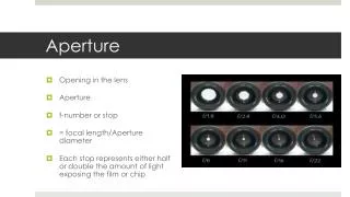
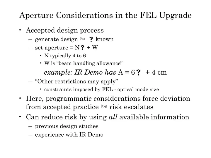
Aperture Considerations in the FEL Upgrade. Accepted design process generate design Þ s known set aperture = N s + W N typically 4 to 6 W is “beam handling allowance” example: IR Demo has A = 6 s + 4 cm “Other restrictions may apply” constraints imposed by FEL - optical mode size

E N D
Aperture Considerations in the FEL Upgrade • Accepted design process • generate designÞ sknown • set aperture =Ns+ W • N typically 4 to 6 • W is “beam handling allowance” example: IR Demo has A =6s + 4 cm • “Other restrictions may apply” • constraints imposed by FEL - optical mode size • Here, programmatic considerations force deviation from accepted practiceÞrisk escalates • Can reduce risk by using all available information • previous design studies • experience with IR Demo
What Do We Know? • No designÞ bunknown • Injector not quantitatively understoodÞ eN135 pCunknown sunknown • FEL optical mode largerÞ3” aperture needed unless we can compress e- beam transport
What Can We Reasonably Surmise? • eN135 pC > eN60 pC • bupgrade> bdemo • larger machine Þlarger b and/or more quads • more quads undesirable • higher cost • increased chromatic aberration (in turn a limit on larger required momentum acceptance) • 1st iteration linac optics (actually, 2nd - 1st was UV Demo design study) has larger beam envelopes • b’s“same” in modules Þ2” may be okay for modules provided emittance does not increase too much • b’s2 x larger in warm regions • triplet focussing needed to handle longer linac, higher RF focussing from increased module gradient Þfor same emittance, need bigger aperture
accelerate 150 MeV 100 MeV 50 MeV 10 MeV 10 MeV 50 MeV 100 MeV 150 MeV energy recover Geometric Emittance Comparison to Demo • bupgrade> bdemo with eupgradegeometric > edemogeometric Þlarger spots • eupgradegeometric > edemogeometric with bupgrade~ bdemoÞlarger spots • eN135 pC > eN60 pC likely, bupgrade> bdemo certain • Injector setup required for high FEL gain (tapered wiggler tests) limited to 1.5 mA by BLM hits Þ2” aperture inadequate even at 60 pC when high gain configuration required?
Conclusion #1 Though 2” possibly (probably?) adequate in modules, peak b’s in upgrade are in warm regions and will drive increase in aperture there Recommendation(s) #1 • Make effort to understand injector quantitatively - and run 5 mA CW at 135 pC • helps define if 2” injector chamber allows reliable operation • characterized normalized emittance at elevated charge • 3” warm region in linac
Linac-to-FEL Transport at 100-200 MeV • It is possible egeometricupgrade < egeometricdemo in the module to FEL transport even with space-charge driven degradation (higher energy) • Þbupgrade> bdemo is washed out in spot size in full energy transport • note that at same energy (mid linac in upgrade, end of linac in demo) spot sizes are larger in upgrade • at low end of energy range (~100 MeV) spots may be same or larger in upgrade due to increased normalized emittance and larger beam envelopes
100-200 MeV beam start 2” 10 MeV beam end 2” optical cavity chicane to wiggler Conclusion #2 2” tube may be adequate for full energy beam from end of linac to start of FEL insertion Recommendation(s) #2
Component Reuse Larger aperture requirements limit component reuse to regions such as linac-to-FEL transport • Diagnostics reusable without modification • QB quads probably reusable without modification • 48 MeV IR Demo QB maximum current ~2 A • QBs spec’d to 10 A with LCW Þcan get to ~200 MeV with 20% headroom for matching • Correctors may prove useful under similar analysis
FEL Insertion Region • Optical mode significantly larger than in IR Demo: • either use 3” aperture (including dipoles) • or restrict matching regions to ~ 5 m length • Current “existence proof” uses ~10 m match • manages aberrations at ±5% momentum offsets by adjusting phase advances amongst telescopes/arc components • causes destructive interference of chromatic effects • y~ òds/b Þ if L reduced, b must reduce • good for small apertures, but, • b smaller Þ quads stronger • stronger quads Þ aberrations larger • higher order chromatics ~quadratic in quad strength, Þ halving lengths doubles quads, quadruples aberrations
3” optical cavity chicane wiggler end 2” Conclusion #3 10 m match “meets spec”Þ5 m match “4 x out of spec” - go with 3” Recommendation(s) #3 • FEL insertion region: • basic optimization for matching telescope length must balance keeping b small - for good performance and acceptance while keeping L large - to limit quad strength • Þ ~10 m match in this machine
Choose magnet families to keep construction simple • fringe models developed for spectrometer magnets; 3” is not “large” so predictive capability likely okay • match magnet gaps in “similar” families • p-bends probably tolerate 2” because b, (and h) “smaller” • power requirements dominated by p-bends (180o out of 300o bending per end loop, so draw most of power) • IR Demo successful matching magnets within and across families; should anticipate similar results in upgrade
Conclusion(s) #4 To avoid undue risk must make FEL insertion 3” “Little” additional cost in making all reverse bends 3” • moderate additional DC power (most in p-bends) • no overhead in “lost” magnets • no dipoles “lost” as none upgrade • need new trim quads, 6-poles, 8-poles due to horizontal aperture increase necessary to accommodate 10% dp/p • significant risk reduction, especially for lower energy operation at higher space charge (can tolerate ~2x larger emittance)
Injection/Reinjection Region - 2” or 3”? bupgrade~2 or 3 x bdemo at reinjection eNupgrade > eNdemo (space charge) egeo.upgrade~ 1/2 to 1/3 egeo.demo (adiabatic damping) Þit will not get better How good is it now? • Cavity 8 tunes a fair bit (Þlosses) • ILM0F062 hits have been limitation • ILM0F06 hits are a limit when running injector for high wiggler gain
Conclusion #5 3” prudent risk reduction at modest incremental cost • new injection/extraction dipoles needed to increase available dynamic range of injection/final energy • “small” magnets (~DU/DV) Þ minor power impact • QJ quads/associated correctors support 3” • need additional quads for recirculator • not enough QBs to populate reinjection region • at very least, need to re-coil some QGs (~4 for linac to FEL transport, this region would require an additional 6 or 7) • could build an additional half-dozen 3” quads