Download
1 / 34
340 likes | 607 Vues
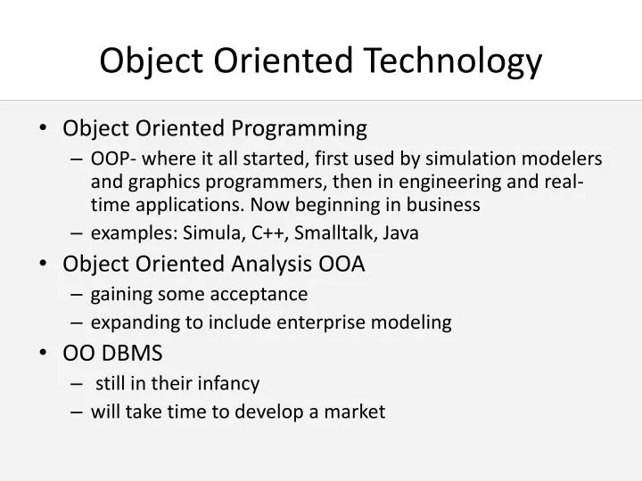
Object Oriented Technology. Object Oriented Programming OOP- where it all started, first used by simulation modelers and graphics programmers, then in engineering and real-time applications. Now beginning in business examples: Simula, C++, Smalltalk, Java Object Oriented Analysis OOA

E N D
Object Oriented Technology • Object Oriented Programming • OOP- where it all started, first used by simulation modelers and graphics programmers, then in engineering and real-time applications. Now beginning in business • examples: Simula, C++, Smalltalk, Java • Object Oriented Analysis OOA • gaining some acceptance • expanding to include enterprise modeling • OO DBMS • still in their infancy • will take time to develop a market
Object Oriented Analysis • Object Oriented programming was designed to deal with the development of software. The concepts used for programming languages are not necessarily appropriate for business analysis. • OO Analysis is designed to deal with the description of an organizational activities. The OOA models developed can then be used to implement system using OO programming techniques
Object Oriented Analysis • OOA combines, in one diagramming technique, both information and the processing that manipulates information • i.e. both DATA and PROCESS • designed to produce a more stable, maintainable IS with reusable components. • represents a “paradigm shift” in analysis, as we no longer consider the problem domain in terms of functions, entities, and data. Instead we consider the domain in terms of Objects and how they interact.
What is an Object? • An object represents an abstraction of state and behaviour of a thing in the modeled domain. • An object’s state is represented as a state variable also known as an attribute • An object’s behaviour is represented by operations or methods that use, return, or modify the value of an object’s state variables
Properties of Objects • 1. Objects possess attributes • Data values carried by objects are made unique by an object identifier (OID) which is assigned by the software • 2. Objects exhibit behaviors (methods) • Methods are the only way that data from the object is accessed or manipulated. • Each method is coded in OO Programming Language (think of each method as a little program) • a method is invoked when an object receives the right type of “message”(request).
Properties of Objects 3. Objects belong to a class A class is a general template used to define specific instances of objects. Example: All objects that capture data about students could fall into a “student” class. This class would contain the attributes and methods that are similar to all students.
Properties of Objects 4. Classes show Inheritance Typically, classes are organized in a hierarchy with more general classes (super classes) at the top and more specific classes (sub classes) at the bottom. Example: Students is a super class for the two sub classes “undergraduate student” and “graduate student)
Properties of Objects 5. Objects interact using Messages Objects communicate with other objects using messages. A message is information sent to an object that triggers that object to perform a particular function. Example: An application for registration form is a message that triggers the registrar to offer or decline registration for a student.
Properties of Objects 6. Object can show Polymorphism The same message can be interpreted differently by different classes of objects. Polymorphism is important because it means that we do not have to be concerned about how something is done, when using an object. The object will react to the message in a (hopefully) appropriate way.
Properties of Objects 7. Objects feature Encapsulation • Messages are sent to objects and they react. • The data and processes contained in the object are hidden away from view. • Concealing the data and internal processes is called: Encapsulation. • All we need to know about an object is: • The set of methods they can perform • What messages (including attributes) need to be sent to trigger them.
So what’s the big deal? • Object-orientation enables analysts to break up complex environment into simpler objects. This enables the development of modular designs. • Modular designs can be reused which reduces effort in development. This saves time and money.
So what’s the big deal? • Some researchers have also suggested that humans conceptualize the world in terms of objects (encapsulated attributes and methods). • In other words, humans may NOT naturally separate attributes from functions. • If that is true…. then using objects for analysis and design may appear more “natural” to individuals than DFD/ERD. Using objects, therefore, may enable people to improve their ability to understand a business domain.
Introduction to the UML • Developed by Rational software and partners beginning in October 1994 • Successor to object oriented languages founded by Rational partners Grady Booch, Ivar Jacobsen, and Jim Rumbaugh • slowly developing as a standard in the software development process, particularly for lower level software design
Goals of the UML • Enable the modeling of systems using object oriented techniques • Establish an explicit coupling between conceptual and executable (code) models • Create a modeling language that could be used by humans and machines • Through standardization, encourage the growth of object-oriented analysis tools • To integrate best practices in analysis, design and implementation *Based on Information from UML summary Version 1.1 September 1997, www.rational.com
What is the UML? • A modeling language that helps to visualize complex software project. • The UML is made up of • model elements • fundamental modeling concepts • notation • the visual rendering of model elements • guidelines • how to combine elements and use the notation
What the UML is NOT • UML is not a Visual Programming Language • there is no code written using UML • UML is not a tool (software package) for building models (although some companies have developed such a tool using UML) • UML is not a process. Two companies do NOT have to use the same process if they both use UML.
Comparing the UML to other Languages • In theory, the UML can be compared to techniques we have learned in this class including DFD’s and ERD’s. • The UML definition covers a large number of concepts (over 233 separate concepts). It is probably more expressive than previous techniques, but it is also more complex than any of the methods we have looked at previously.
Modeling in the UML • There are four main modeling methods in the UML that we will focus on. • Use Case Diagrams (overview) • Object Class Diagrams (static) • Sequence Diagrams • Behavioral State Machine Diagram
What is a Use Case Diagram? A Use Case model is made up of actors and use cases. Actor Use Case An actor “uses”the system. The Use Case documents what happens when the user initiates the interaction. A use case is always initiated by an Actor. A sequence of transactions that shows the dialogue between users and the system. A “use case: is one specific way that an actor uses the system.
A Use Case Diagram Example: Part 1 Starts with a simple interaction diagram Fast Food System Customer Service Person Applicant Manager Supplier
Use Case Diagrams • Use Cases can interact with each other. There are two types of interactions: <<extends>> • adds to an existing use case by adding new behaviour or actions. • For example: registering for a special course, extend the use case for registering for a normal course. See diagram 12-2. <<includes>> • when one use case uses another use case. The arrow points to the use case being used.
Car Rental Example Check Availability Check Rates Sell Gas Sell Insurance Corporate Billing <<includes>> <<includes>> <<extends>> <<extends>> <<extends>> Book car Pick Up Car Customer Rental Clerk Return Car
Use Case Diagrams and DFDs • A use case diagram is like a context diagram, but includes all the processes separately • The individual use cases are like a DFD fragment • Differences: • In OO modeling, the automation boundary is drawn first • In OO modeling there may be a mixture of levels (unlike the DFD, where level 0 and level 1 are kept separate • A use case diagram does not indicate data flows
Object Name Next: Object Class Diagrams • Class Diagrams show the structure of the system (similar to entity relationship) • Basic Symbol: the object and association Object Object Name:Class Name Or a simpler notation Attributes Methods
Class diagram concepts • A static model that shows the classes and relationships among classes that remain constant in the system over time • Resembles the ERD, but depicts classes which include both behaviors and states, while entities in the ERD include only attributes
Elements of a class diagram • Class – people, places, events and things • Attributes – properties of the class • Methods – actions or functions that a class can perform (show only those that are unique to a class) • Constructor methods (create new instance) • Query methods (makes info available, but does not alter it) • Update methods (change value of all or some attribute • Relationships (or associations)
Association • Lower bound..Upper bound • 0..1 zero or one • 1..* one or many • * unbounded
Object Class Diagrams Object Name: Student Name ID Number Faculty Address Phone Calc GPA ( ) Register-for (course) printTranscript ( )
Class Diagram for “Rent DVD” Video rental Cust_number Video_ID Date rented #rental days Date returned Rental status Condition Customer Video Cust_number Cust_name Cust_address Cust_phone Video_ID Video_title Video_genre Video_release date 1 0..* 0..* 1 +change status +calculate late fee
Steps in creating a class diagram • Identify classes • Identify attributes and operations • Draw relationships between classes
Behavioral State Machine Diagram • A dynamic model showing changes of state (changes in central attributes) of a single class over time in response to events, along with its responses and actions • Typically not used for all classes, but just to help simplify the design of algorithms for methods of complex classes