Download
1 / 33
330 likes | 475 Vues
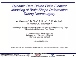
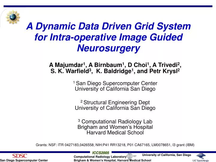
A Dynamic Data Driven Grid System for Intra-operative Image Guided Neurosurgery. A Majumdar 1 , A Birnbaum 1 , D Choi 1 , A Trivedi 2 , S. K. Warfield 3 , K. Baldridge 1 , and Petr Krysl 2 1 San Diego Supercomputer Center University of California San Diego

E N D
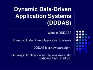
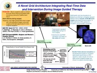
A Dynamic Data Driven Grid System for Intra-operative Image Guided Neurosurgery A Majumdar1, A Birnbaum1, D Choi1, A Trivedi2, S. K. Warfield3, K. Baldridge1, and Petr Krysl2 1 San Diego Supercomputer Center University of California San Diego 2 Structural Engineering Dept University of California San Diego 3 Computational Radiology Lab Brigham and Women’s HospitalHarvard Medical School Grants: NSF: ITR 0427183,0426558; NIH:P41 RR13218, P01 CA67165, LM0078651, I3 grant (IBM)
TALK SECTIONS • PROBLEM DESCRIPTION AND DDDAS • GRID ARCHITECTURE • ADVANCED BIOMECHANICAL MODEL • PARALLEL AND END-to-END TIMING • SUMMARY
Neurosurgery Challenge • Challenges : • Remove as much tumor tissue as possible • Minimize the removal of healthy tissue • Avoid the disruption of critical anatomical structures • Know when to stop the resection process • Compounded by the intra-operative brain shape deformation that happens as a result of the surgical process – preoperative plan diminishes • Important to be able to quantify and correct for these deformations while surgery is in progress by dynamically updating pre-operative images in a way that allows surgeons to react to these changing conditions • The simulation pipeline must meet the real-time constraints of neurosurgery – provide images approx. once/hour within few minutes during surgery lasting 6 to 8 hours
Brain Shape Deformation Before surgery After surgery
Preoperative Data Acquisition Segmentation and Visualization Preoperative Planning of Surgical Trajectory Preoperative data Intraoperative MRI Segmentation Registration Solve biomechanical Model for volumetric deformation Surface matching Visualization Surgical process Overall Process • Before image guided neurosurgery • During image guided neurosurgery
Timing During Surgery Time (min) 0 20 30 10 40 Before surgery Duringsurgery Preopsegmentation IntraopMRI Segmentation Registration Surfacedisplacement Biomechanicalsimulation Visualization Surgicalprogress
Pre and Intra-op 3D MRI (once/hr) Segmentation, Registration, Surface Matching for BC Intra-op surgical decision and steer Once every hour or twofor a 6 or 8 hour surgery Local computer at BWH Merge pre and intra-op viz Crude linear elastic FEM solution Current Prototype DDDAS Inside Hospital
Current Prototype DDDAS System • Receives 3-D MRI from operating room once/hour or so • Uses displacement of known surface points as BC to solve a crude linear elastic biomechanical FEM material model on compute system located at BWH • This crude inaccurate model is solvable within the time constraint of few minutes once an hour on local computers at BWH • Dynamically updates pre-op images with biomechanical volumetric simulation based intra-op images • Time critical updates shown to surgeons for intra-op surgical navigation
Two Research Aspects • Grid Architecture – grid scheduling, on demand remote access to multi-teraflop machines, data transfer • Data transfer from BWH to SDSC, solution of detail advanced biomechanical model, transfer of results back to BWH for visualization need to be performed in a few minutes • Development of detailed advanced non-linear scalable viscoelastic biomechanical model • To capture detail intraoperative brain deformation
Example of visualization: Intra-op Brain Tumor with Pre-op fMRI
Queue Delay Experiment on TeraGrid Cluster • TeraGrid is a NSF funded grid infrastructure across multiple research and academic sites • Queue delays at SDSC and NCSA TG were measured over 3 days for 5 mins wall clock time on 2 to 64 CPUs • Single job submitted at a time • If job didn’t start within 10 mins, job terminated, next one processed • What is the likelihood of job running • 313 jobs to NCSA TG cluster and 332 to SDSC TG cluster – 50 to 56 jobs of each size on each cluster
Average queue delay for tasks that began running within10 mins
Queue Delay Test Conclusion • There appears to be a direct relationship between the size of request and the length of the queue delay • Two clusters exhibit different performance profiles • This behavior of queue systems clearly merits further study • More rigorous statistical characterization ongoig on much larger data sets
Data Transfer • We are investigating grid based data transfer mechanisms such as globus-url-copy, SRB • All hospitals have firewalls for security and patient data privacy – single port of entry to internal machines Transfer time in seconds for 20 MB file
Current and New Biomechanical Model • Current linear elastic material model – RTBM • Advanced model under development - FAMULS • Advanced model is based on conforming adaptive refinement method – FAMULS package (AMR) • Inspired by the theory of wavelets this refinement produces globally compatible meshes by construction • First task is to replicate the linear elastic result produced by the RTBM code using FAMULS
FEM Mesh : FAMULS & RTBM RTBM (Uniform) FAMULS (AMR)
Deformation Simulation After Cut No – AMR FAMULS RTBM 3 level AMR FAMULS
Advanced Biomechanical Model • The current solver is based on small strain isotropic elastic principle • The new biomechanical model will be inhomogeneous scalable non-linear viscoelastic model with AMR • We also want to increase resolution close to the level of MRI voxels i.e. millions of FEM meshes • Since this complex model still has to meet the real time constraint of neurosurgery it requires fast access to remote multi-tflop systems
Parallel RTBM Performance (43584 meshes, 214035 tetrahedral elements) 60.00 50.00 IBM Power3 40.00 Elapsed Time (sec) 30.00 IA64 TeraGrid 20.00 IBM Power4 10.00 - 1 2 4 8 16 32 # of CPUs
End to End (BWH SDSCBWH) Timing • RTBM – not during surgery • Rendering - during Surgery
End-to-end Timing of RTBM • Timing of transferring ~20 MB files from BWH to SDSC, running simulations on 16 nodes (32 procs), transferring files back to BWH = 9* + (60** + 7***) + 50* = 124 sec. • This shows that the grid infrastructure can provide biomechanical brain deformation simulation solutions (using the linear elastic model) to surgery rooms at BWH within ~ 2 mins using TG machines • This satisfies the tight time constraint set by the neurosurgeons
DURING SURGERY End-to-end Timing of Rendering • MRI data from BWH was transferred to SDSC during a surgery • Parallel rendering was performed at SDSC • Rendered viz was sent back to BWH (but not shown to surgeons) • Total time (for two sets of data) in sec =2*53 (BWH to SDSC) + 2* 7.4 (render on 32 procs) + 0.2 (overlapping viz) + 13.7 (SDSC to BWH) = 148.4 sec
Ongoing and Future DDDAS Research • Continuing research and development in grid architecture, on demand computing, data transfer • Continuing development of advanced biomechanical model and parallel algorithm • Moving towards near-continuous DDDAS instead of once an hour or so 3-D MRI based DDDAS • Scanner at BWH can provide one 2-D slice every 3 sec or three orthogonal 2-D slices every 6 sec • Near-continuous DDDAS architecture • Requires major research, development and implementation work in the biomechanical application domain • Requires research in the closed loop system of dynamic image driven continuous biomechanical simulation and 3-D volumetric FEM results based surgical navigation and steering